

Joe Guilbeau's Alternator Theory Page
(Depending on your connection speed, this may take a short while to load due to the number of graphics in the page).
01/20/04 Version 15
Click here for a printer friendly page
Section 1…“Alternators 101”
Section 2…”Delco 10-SI and Delco 12-SI Alternators used in
our Jeep applications”
Section 3…”The CS-130, CS-130D and
CS-144…now referred to as “Generators” by Delco!
Section 4…”Some practical upgrades for the do it yourselfer (DIY)”
Section 5…“How to Guide”
upgrades for you penny pinchers out there…”
By the way, what IS a good, easy, simple, semi-foolproof method for testing one’s alternator?
That anyone can do?
No training required and only a valid Drivers License may be required, and perhaps an AM radio.
Well, at night one
may pull up to a wall with one’s headlights on High Beam, turn off everything
else that is drawing power, and have the vehicle at idle.
Sit there for about a minute noting the brightness of the headlights.
Kill the engine, and note the change in headlight intensity. You should notice one of the follow three occurrences…
1…. Headlights get brighter when the engine is killed…The alternator is not putting enough charge into the battery, when the engine is killed, there is less load on the battery
and therefore more battery amps are available, so the lights get a bit
brighter. Alternator requires service.
2…. Headlights get dimmer when the engine is killed…the alternator is keeping up with the demand that the headlights are putting on the battery, and is charging normally. When
the engine is killed, the headlight continue to draw from the battery, however
the battery is no longer supplemented by the alternator, and therefore there is
less voltage/current that is being delivered to the headlights, ergo the lights
get dimmer. Alternator is operating normally.
3…. Headlights do not change in intensity…Congratulations, that is some battery you have…Optima
perhaps?
Alternatively (pun intended), a faulty diode may induce interference in the RF Frequency, or RF
noise range, and this might induce an audible whine on the AM radio, very easy
to check when you find that the battery is being discharged overnight.
So, while doing the above headlight testing, when the engine is running at constant rpm’s, turning off/on the headlights will put a load on the alternator, and at constant engine
speed if you detect an AM radio interference that comes and goes with the
additional headlight load, this may indicate that the regulator circuit (diode/s) is suspect.
If you vary the engine rpm’s, and the AM Radio Interference tracks the engine speed, then
perhaps the bearings or the belts need servicing, or this problem might even be
the spark plug wires or the noise suppressor circuit gone bad.
Unplugging the alternators regulator circuit may halt the RF interference; this is a pretty
good indication that the Regulator circuit (diodes) is to blame. Some
manufacturers recommend disconnecting the battery first, so please be aware of
the recommended procedures and follow them. Do not EVER disconnect the battery
cables when the engine is running, this is no longer a viable way to test
alternators and will ruin many of the versions that are in use today.
In the diode rectifier circuit, the alternating current ripple voltage might be measured
with AC multimeters, you should probably go out and do a quick measurement
across the battery terminals to log a “normal” reading when you have a known
good alternator and regulator for A/B comparisons at some later date, when you
suspect that there might be a problem.
Less than optimal connections may also result in high impedance, which in turn, might increase RF noise.
If you understand/don’t care about the electrical characteristics of how magnetism is
created in field windings and harnessed for use in alternators, please go ahead
and skip this portion, and move on to “Section 2”.
Otherwise, read on for a brief discussion of what is happening in the world of electricity,
electronics and regulators, field magnetism, diodes and how it all comes
together to keep our FSJ’s squared away. This is not very technical, and is
pretty generic, to boot.
By the way, even the
best minds in science do not know what electricity really is, what we do know
is how to harness it, but nobody really can tell you what “it” is.
We can quantify,
measure and harness it, but we are just not positive what holds those pesky
electrons/protons together.
I find this somewhat
refreshing.
This is a physics
property that occurs in metallic structures, covalent bonding has a lot to do
with the nature of the electron flow, go figure….
As Scotty of “Star
Trek” fame was fond of saying…”Ya cannot change the laws of physics, Captain…”
Make a fist with
your right hand, and do a “thumbs up”, and hold your fist in front of you, now
extend your forefinger like you are pointing at something, the forefinger and
the thumb will be at a 90 degree angle from each other. Now if you take your
right middle finger and make a 90-degree angle with the forefinger, your middle
finger will be pointing to the left across the chest area.
Holding the fist in
this orientation, and not moving the position of the fingers and thumb, if you
point your thumb in the direction that the conductor is going to be moved thru
the magnetic field, and the forefinger in the North to South direction of the
magnetic flux, the middle finger will point in the direction that electron
current will flow.
This is similar to
slicing that loaf of bread, if we cut it at an angle, the knife has to travel
longer to cut thru the same vertical distance of the loaf, and transferring
this “bad analogy” to the alternator, magnetic lines of force can be cut at 90
degrees, and thus travel a shorter distance in a given period of time. Thus
they cut more magnetic lines of flux in a shorter time frame, thus generating
increased voltages. Cutting that loaf of bread at a greater angle cuts the same
number of magnetic lines of force, but the blade has to travel a greater
distance, and takes a bit longer to complete.
So, now we have a
dense magnetic field and as the engine speed of the vehicle increases, we can
see how the density of that magnetic field increases. As this magnetic field is
rotated, an induced Electro Motive Force is created in the three phase stator
windings that are 120 degrees apart.
Here is a hint…want
to know if the brushes on the alternator need replacing, put a screwdriver
against the alternator, being careful not to get it hung up on anything, and
check out the magnetism that the alternator puts out. With time, you can “feel”
the difference in magnetism intensity, and judge “good” brushes and “bad”
brushes.
Each stator loop coil creates a 360-degree voltage that is known as a sine
wave. The induced voltage gradually increase until the angle is at 90 degrees
(peak induced voltage and low current flow), and as the angles decrease again,
the voltage decrease correspondingly (as the current increases); until the
magnetic field begins to approach another set of stator loops or coils of wire,
and the process starts all over for that particular loop coil, see the below
picture to visualize this process.
In our alternator example, we have three loops of wire, and these three loops
are placed such that a sine wave in each loop is generated. A complete
revolution of the rotor assembly, which is 360 degrees of revolution, gives us
three overlapping voltages that are 120 degrees apart (360 divided by 3 equals
120). The configuration of the windings (and associated diode rectification
configuration) causes these Alternating Current (AC) sine waves to overlap each
other, as depicted below.
Once the AC voltages are created, we need to modify them because our Jeeps run
on 12Vdc. The battery is responsible for supplying power to the electrical
loads, and the alternator is responsible for keeping the charge rate of the battery
within design limits.
Electronic components in the regulator circuit smooth out this voltage, in
order to generate the 13.5Vdc to 14.8Vdc required by the battery for topping
off its charge. The various regulators associated with alternators are
responsible for this engineering feat.
Speaking of Rotors
and Stators, here is a simple trick that helped me distinguish them from each
other.
Rotor… to rotate
Stator…stationary
KISS, eh?
One of the other
rather “odd” situations out there revolves around some “OEM Regulators”; early
on it seems that the automotive battery could discharge thru the
regulator/ignition switch when the ignition switch was turned off and the
points happened to be closed.
This provided a
leakage path to drain the battery, in an automotive application; this could
take a month or so. The tractor guys brought this “feature” to light, after
all, a battery in an auto is likely to be started at least once a month, and as
such this parasitic draw was not very noticeable.
I will leave it to
others to explain valence electrons and positive ion flows, I will just say
that opposites attract, and pass over the details at this time.
Now, lets get on
with some technical details on FSJ alternators…
Section 2…”Delco 10-SI and Delco 12-SI Alternators used in our Jeep
applications”
Return to Top
Image 008
These were the 1st generation of Delco/Remy System Integral (“SI”) alternators, meaning that the regulator was mounted inside the alternator, instead of being a separate unit
on the firewall, and began showing up in the very early 70’s in GM products it
weighed in at about 10.5 lbs. This becomes quite a handful when replacing in
some vehicle applications.
With all OEM components installed they had outputs of 37-amp, 42-amp, 55-amp, 63-amp,
70-amp, and 85-amp (according to my ’83 TSM) ratings, outputs higher
than 100 amps can be purchased but the heat dissipation and cooling
requirements needed are just not incorporated into these units, therefore most
if these higher output conversions are simply not recommended.
Cooling is accomplished via three vertical slots on the rear
housing and a pulley mounted cooling fan. The heated air from the passenger
side exhaust manifold is drawn into the housing. The threaded mounting hole and
orientation of the regulator connections determined the “clocking” of an
alternator (see Image 003).
Amp’s/RPM’s of 40 Amp unit
.0 amps at 1600 alternator rpm’s/40 amp model font-size:12.0pt;.0pt;
30 amps at 3000 alternator rpm’s/40 amp model
36 amps at 4000 alternator rpm’s/40 amp model
Amp’s/RPM’s of 63 Amp unit
Delco SI-series internally regulated alternator have the following connections.
One large connection that is the Alternator output, known as the Bat, this connection has
"Bat" cast into the housing (aftermarket housings may not incorporate
these markings). Two additional tabs (inputs to the internal regulator) are
used to interface the vehicles wiring harness, these have "1" and
"2" cast into the housing next to them. A two terminal Molex
connector is generally used to connect the wiring harness to the regulator
circuit.
Here are the details on the individual terminals:
"Bat"- this terminal is for the alternator output to the battery. On some jeeps this
output goes directly to the ammeter inside the cab, and returns and has a
fusible link in series somewhere along the line. Later versions used a
voltmeter, and this terminal went to the solenoid and on to the Pos-Terminal of
the battery.
Nichrome wire is difficult to solder to, and it is getting hard to find insulated versions of it, notably due to the fact that traditional usage is for a heating element for cutting foam products and these applications do not need the insulating wire jackets.
What you want is a Vishay-Dale RH-50 series power resistor in 15-ohms. It is an aluminum heat sink encased environmentally sealed power resistor that can be bulkhead attached and your wiring soldered and heat shrink insulated to the termination lugs. Operating Temperature range is -55 C to + 250 C good for anywhere on the planet earth. The model number would be RH0505015R00F. http://www.vishay.com/docs/30201/30201.pdf
Quick, simple and fairly cheap, less than $10 dollars for one shipped to your door. A distributor called electrospec should have some in stock... http://www.electrospec.com/account/rfqcart.asp
The lamp limits the voltage to the "Field" terminal, and this current
limited voltage is what tells the regulator to start/continue/stop charging.
When the alternator begins to charge, the voltage increases at the battery.
The Number two terminal above is connected to (most likely) the solenoid
terminal hooked to the positive post of the battery, or is set up a for remote
sense (the preferred voltage monitoring location), and connects to the braised
or soldered fan-out connection, and senses the charge condition of the battery,
and routes this voltage to a voltage divider network (R2/R3) with a capacitor
(C1) to filter it inside the regulator circuit. This voltage divider network
limits the current discharge to negligible amounts.
In the charging mode the circuit operates in the following manner…
The regulator circuit is now being fed from Terminal 1, which provides base drive to TR1,
thru R1 and D1. D3 is reversed biased and is blocking current flow. With base
drive, TR1 is forward biased, and it acts like an “On/Off” switch. When it is
on, it provides a path for current to flow from the rotor’s field windings
(supplied by Terminal 1) to ground thru its emitter/collector junction. Therefore
the alternator is charging at this point, because current is flowing from the
ignition switch thru the No. 1 Terminal on the alternator, thru the field
windings coil and continues on thru the emitter/collector junction of TR1, and
to ground.
The lamp circuit cannot supply enough current to the field windings to sustain or generate the
magnetic field in order to induce a voltage output on the Stator windings. So,
in many applications the vehicles engine must be revved to a higher RPM in
order to generate enough initial field strength so that the induced EMF is
sufficient to self maintain it.
The battery is now being charged by the alternator, and therefore its voltage begins to rise. The voltage divider network (R2/R3 which is factory adjusted) begins to see the
voltage across R3 rising, in time the alternator charges the battery
sufficiently so that the voltage rise across R3 reaches a threshold. This
threshold voltage forces Zener diode (D2) to be biased into conduction, which
in turn provides TR2 transistor with base drive.
TR2 transistor’s base to emitter is now forward biased and therefore its collector voltage is
essentially “switched” to a diode drop potential above ground. This turns off
base drive to TR1, which “switches off” and no longer provides a path for the
rotor field current circuit, and the rotor field collapses, because there is no
longer any current flowing thru its coil.
Bringing the junction of R1 and the Cathode of D1 to ground potential results in reverse
biasing the cathode/anode junction and therefore the Base to Emitter junction
of TR1 is now reversed biased and it no longer conducts and switches off.
The following diagram illustrates the point, as the base drive controls the “On/Off
switching” of TR1… when the switch is on, the rotor coil current flows, when
the switch if off, no current flows in the rotor and the field collapses.
Thus the alternator generates Alternating voltage and current. A diode trio
rectifies the current that flows through a transistor, which feeds the field
windings of the rotor, self excitation if you will…don’t even go there, I’ve
heard it all before.
Anyone still with me…?
Each regulator circuit has its own designs and circuitry, which may very well differ from the
specific description above. The above example was given to illustrate the basic
operating principals of the regulator circuit, and happens to be the circuit
that is generally on the 10=SI and 12-SI units.
The cooling fan on a Delco 12-SI alternator is easy to spot, as it backs up the alternator pulley and is a black thermoplastic with a metal plate attached between the fan and
the pulley for added strength. I am referring to the OEM alternators here.
These models began appearing around 1983. With under hood real estate becoming
a premium and greater electrical loads making demands on the alternators, the
12-SI with it’s increased cooling and higher output became a popular component.
Larger air intake ports on the rear of the alternator also contributed to
cooling. These units can be purchased from aftermarket vendors up to 140 amps.
The interior and cooling components incorporated in these units make this
feasible.
Just to reiterate the point, the cooling fan is actually an EXHAUST fan, which draws air from the back of the alternator (which is butted up against the engine and the passenger
side exhaust manifold) and pulls this heated air (from the rear of the
alternator past the rectifier heat sink towards the front housing), this
superheated air is now routed towards the front of the vehicle. As you can see
in the illustration below, the cooling vents are against the engine and exhaust
manifolds in our Jeeps, and the fan pulls this heated air thru the alternator
to “cool” it’s electronics…
Improvements in the regulator circuit designs have occurred but the operation is basically the same as in the 10-SI Series. These units are pretty tough and usually give years of
service. .
. The illustrations above depict a typical CS-130 and CS-121 view.
CS-130D
CS-130D Dimensions
The rest of this post refers to the Delco CS units (CS-121, CS-130 and CS-144) CS stands for
Charging System and the 121, 130 or 144 number behind a CS-*** refer to the
outside diameter of the stator in millimeters.
The Delco CS-series alternators are supplied in 61-amps, 70-amps, 72-amps, 74-amps, 80-amps,
85-amps, 96-amps, 99-amps, 100-amps, 102-amps, 105-amps, 108-amps, 124-amps,
and 140-amps and 145-amp configurations.
The below active link is a reference page that I pulled the above information from…as I mention, there are many configurations. Just be aware that there are many CS-Series
regulators out there in re-manufactured units.
CS-144 Cutaway
For those of you with an interest, the Patent for the CS 130 Bridge Rectifier is presented
below. These regulators are essentially computer chips now, and feature surface
mount technology and a host of other features.
I mention this so that the reader might come to the conclusion that one may not treat these
“regulators” in the same fashion as the earlier more rugged designed
regulators.
Page one of PATENTS 4,606,000 August 12, 1986, BRIDGE RECTIFIER (Bridge Rectifier for CS130
generator).
http://patft.uspto.gov/netahtml/srchnum.htm
The above link will allow you to input the Patent number
(4,606,000) as a “search string”, in order to view the patent information
submitted to the US Patent Office.
You may view pages 1-15 of the original patent for the
CS-130 Alternator and the Bridge Rectifier as granted on August 12th,
1986.
I like patent info, some of the BS out there is really
incredible, and a little research at the US Patents Office can shed some light
on what is real and what is hype.
Aftermarket ignition systems come to mind here, I like MSD!
You must have a reader in order to access the patent
information, the reader is free, go to the URL below to get the free reader,
after you choose the correct version for your OS, you can load the free reader
and take a look at the images that were filed as part of the Patent process
(Engineering Design Drawings, Mechanical CAD/CAM).:
10.
http://www.uspto.gov/patft/help/images.htm#not
For some preliminary information of the images, I have cut and pasted some data on
the image formats…
“…PTO's full-page images, nearly four terabytes overall, are stored and delivered at
full 300 dots per inch (DPI) resolution in an image file format called
"TIFF," using CCITT Group 4 compression. This is the format, which is
required by the international standards to which all patent offices must
conform. TIFF is also the most used image format in the world. Unfortunately,
due to the volume of the image data, available funding, and other technical
considerations, PTO cannot convert these images to a format more popular on the
Web either permanently or by converting on the fly as they are delivered.
As a result, you must install and use a browser plug-in -- similar
to those required to access Adobe® PDF files, RealPlayer®, or Macromedia Flash®
files -- on your workstation in order to view these files directly. An
alternative method is to use third-party software or services to view these
images either directly or after conversion to another format, such as Adobe®
PDF.
The plug-in you use cannot be just any TIFF image plug-in. It must be able to
specifically display TIFF files using ITU T.6 or CCITT Group 4 (G4)
compression.
The only free, unlimited time TIFF plug-ins offering full-size, unimpeded patent
viewing and printing unimpeded by any advertising on Windows® x86 PCs of
which we are aware are.
Well, enough on the US Patent Office and Patents…
After the introduction of the CS-130, Delco modified the alternator and came up with the
CS-130D. This translates to a Charging System with a 130 mm diameter stator
with a dual internal fan set up (D-designator). The CS-130 also had dual fans,
one external mounted next to the pulley, and one internal fan mounted on the
rotor designed to cool the rectifier, regulator and bearing, while the CS-130D
has BOTH fans mounted internally.
Early CS-130’s were issued with 8mm bearings and were later upgraded to more durable 10mm bearings for improved service life. There is an “Iceberg Kit” for these alternators that
includes a replacement housing, larger bearings, and pumps up the alternator
output to up to 140 amps or so, for around $90 dollars. A bit more on this
later.
The CS-130D has one additional safety feature, if the internal temperature of the alternator rises above 280 Degrees F, the unit shuts down, and you must wait until it cools
down, before the unit will operate in a normal fashion.
So overloads on this particular alternator, causing excessive charging rates to occur, may actually cause it to heat up and shut down….so there you are sitting in Phoenix traffic
in August and you notice that the voltmeter is telling you that the alternator
is no longer functioning, so you find a place to pull over and have it tested.
Run DMC is rocking your world, and this is screwing up your vibe…
What with waiting in line, and getting the vehicle set up, it is something like 30 minutes later or the next day that the tech tests the vehicle.
Volia!…nothing is wrong. Your temper is at max…film at eleven!
No one was wrong, everyone was right in this situation…go figure, the more you know….
So, get those batteries fully charged. Some might think that alternators are designed to
charge batteries, but this is really not the case, they are designed to maintain
a fully charged battery, there is a distinction and the reader would do well to
become aware that this distinction exists.
These alternators incorporate higher efficiencies with improved cooling. They utilized a pulse
train control to manipulate the magnetic field strength via pulse width
modulation of a 400 Hz pulse train. This generally means that inputs to the
magnetic field are more gradual, and therefore the alternators output will
respond in the same gradual manner. The duty cycle (how long the pulse stays on
and off) can be controlled in order to create a “soft start” capability that is
easy on things like electronics and computers and such.
There are 2 cooling fans used in the CS-130’s, and internal unit and an external unit, the alternators are smaller and more efficient that their predecessors. Recall that the
CS-130D’s utilize dual internal fans.
For further cooling, try out the “Iceberg Housings”, which add cooling fins over the regulator area for additional heat sinking properties, as shown below. National Quick Start
has a kit to upgrade the CS-130’s to 140 amps, reusing the front half of the
housing, your existing rotor, the voltage regulator, plastic fan dust shield,
fan, pulley and the hardware. You get a new rear housing similar to the one
below and new upgraded stator, rectifier and heat sink, new larger bearings;
all for about $100 dollars. So, go find that used CS-130 (look for brand new
shiny ones, as they are generally supplied by the OEM Delco manufacturer and
may be found on late 80’s GM vehicles for about $20 dollars) and buy the
“Iceberg Upgrade Kit” kit, then you will be set.
Here is an “Iceberg Kit” from Quick Start (see below image),
and it is a re-builders kit for the CS-130 and also a kit that will increase
the output amps to 140-amps, the below image is for the standard upgrade kit
only.
Standard "Iceberg Alternator"™ kit contains: (for
the above image and taken from Quick Start site)
Step-by-Step Instructions
In the Image below, you can see the kit for the 140-amp
upgrade as it includes the additional re-wound stator.
140 Amp "Iceberg Alternator"™ kit contains: (for
the above image and taken from Quick Start site)
Getting back to the CS-series alternators, the diode trio’s that were used in the “SI-series”
alternators have now been dropped, and the CS-series use avalanche diodes
instead, that are capable of handling 55 or so amps in the better
regulator/rectifier circuits, such as OEM supplied components.
There are at least 14 Application Specific Voltage Regulator (ASVR) aftermarket
regulators for the CS-series alternators that I personally know of, and I
certainly do not know them all. Delco calls their rectifiers All Silicon
Voltage Regulators (ASVR), alluding to the fact that these upgraded regulator
designs are indeed computer chip designs. They also refer the alternators as
“Generators” now.
These regulators are what are referred to in the electronics industry as Application Specific
Integrated Circuits (ASIC’s), and as such, the original designs by Delco/Remy
have been reversed engineered by aftermarket vendors in order to make a higher
profit margin by providing their own versions of these regulators in
remanufactured/rebuilt alternators. Some aftermarket units are better than
others; none are likely to be as reliable as OEM…or as expensive!
Earlier we discussed the 10-SI and 12-SI regulator circuits, where transistors were used to provide a solid-state switch for the return path of the field voltage. These have been
in use for many years.
Note that while the overall concept is the same for the CS-series generators, the “base drive” to switch the field magnetic strength on and off is now controlled by pulse width
modulated train of varying duty cycle pulses that controls the density of the
induced EMF on the field windings and gives greater and finer control over the
Stator winding output. Thus the term ‘Generator” is now being used by Delco.
CS-130 Series Voltage Regulator/Rectifier
In the above schematic, you can see how a voltage divider circuit can be utilized in order
to give the end user further control of the regulator as one might wish to send
the “S-Terminal” (Regulators sense voltage) a lower voltage, thus causing the
regulator to slightly increase the alternators output. This might be used to
mitigate some additional loads on the alternator, especially if switched in on
a vehicle whose RPM range will not get much above idle and excessive amperage
loads are used such as rock crawling in the night. As a side note, please be
aware that the above configuration may not work on all CS-series regulators.
Some regulators will respond fine just using the S-Terminal as depicted above
and no Lamp connection. Some CS-series regulators may only require the
I-Terminal to be connected to an Ignition Source, and therefore will work fine
without any other wiring connections.
Section 4…”Some practical upgrades for the do it yourselfer (DIY)”
The CS-series of alternators use a 4 terminal regulator, with terminals designated as PLIS or
PLFS, commonly referred to as PLI/FS. It is next to impossible to know if a
PL(I)S or a PL(F)S regulator is in the unit, you have to take the case apart
and check the part numbers on the regulator. There are apparently methods to
bench test and determine the regulator type, but this is best left to folks who
have access to the various cross reference documentations and is beyond the
scope of this particular article. The documentation may be purchased at outlets
that support the alternator servicing community. If you know the make and
manufacture of vehicle that the alternator is designed for, then you can track
it down.
Some of the regulator circuits stamp either the “I-designator” or the “F-designator” on the
plastic housing; others however do not do this. Just be aware of the ions.
Some regulators have PLI/FS terminal markings, so it can get confusing at
times.
Another caution is in order here; the ASVR and earlier regulators in the CS-Series alternators can easily be damaged by improper servicing techniques. Please observe the
following precautions when removing or installing these alternators.
Removing CS-Series Alternators…
Always disconnect the Negative Battery Cable before doing anything
Installing CS-Series Alternators…
Always disconnect the Negative Battery Cable before doing anything!
10. The CS terminals are designated as follows:
L-Terminal: This terminal is connected to the “Low” side of the warning lamp, with the lamp’s
“High” side being fed by the ignition circuit. Some regulators require a 35-ohm
resistance inline with this circuit if no lamp is used otherwise alternator
damage may ensue. Some applications have a resistor connected in parallel to
the lamp in case the lamp bulb opens up and burns out. The resistor will be
there to provide a path for current and voltage. Some vehicles supply a 5Vdc
reference to this terminal from their ECU or Computer; other vehicles don’t, so
be aware of the various models of regulators. Other regulators may be tested by
application of a 50-Ohm pull-up resistor to connect the L-Terminal to the 12Vdc
source, I believe that any resistance between 35 Ohms (5-Watt resistor) and 500
Ohms (1/2 Watt resistor) can be used safely.
The CS-130D Alternators have the following connections…NOTE: All of the Terminals on the
CS-130D regulators are the same size.
P-Terminal: Provides a 12Vdc square wave as in the CS-130 application.
F/I-Terminal: It gets a bit tricky here, as some applications do not incorporate a lamp circuit. In vehicle applications of the “no lamp” kind, this terminal is connected to
the Ignition Switch, and an internal resistor is used to limit current and
voltage. Other regulators use this terminal as an output and refer to this pin
as a Field Terminal, as such, it provides an output that is proportional to the
field duty cycle of the alternator to an a vehicles ECM. The ECM now has an
input to sense alternator loading and engine loading, and can increase/decrease
engine speed accordingly. Here is an important consideration, since the
regulators on CS-130D type alternators have these two different types of
regulators (F-Type or I-Type) they cannot be interchanged. I-Type regulators
use the F/I-Terminal as an input and this can simply be an ignition source
12Vdc voltage that the alternator uses; F-Type regulators use the F/I-Terminal
as an output (this ion is a signal that is provided to the vehicle computer
and the computer uses it to monitor the field intensity of the alternator as an
input. If you supply a 12Vdc signal to this input, you may very well ruin the
alternators regulator.
L-Terminal: This is the lamp terminal and operates in the same manner as the CS-130 lamp circuit above. It is of interest to note that some applications use the ECM to send the
L-Terminal a signal (5Vdc reference), and the F-Terminal responds with a signal
sent to the ECM, in this application the ECM and the Regulator form a “closed
loop” to control engine loading and alternator output.
S-Terminal: This is the “Sense” terminal and is connected to the battery. It senses the voltage
level of the battery and feeds the regulator circuit this reference so that the
regulator can adjust the Pulse Width Modulation to control the alternators
output. The S-terminal on the CS-130D regulator is the same size as the other
three terminals, unlike that of the CS-130.
There is an up and a down side to using these devices. On the up side, they prevent damage and
surges, current spikes, and such from reaching sensitive electronic equipment
inside the cab and under the hood.
On the down side, due to the nature of their operation, their lifespan is not as long as the
earlier diode trio’s used in 10/12-SI alternators. Still, many years of service
can be expected, just not decades as in earlier alternators, I believe that the
service life of the CS-series alternators is somewhere around 80,000 to 100,000
miles depending upon specific model number (CS-121, CS-130, CS-130D and CS-144.
As an aside on the subject of diodes used in the CS-130D series of alternators, consider the
following. A CS-130D with an output of 105 amps uses a three-phase stator with
a 6-diode bridge rectifier. Each forward biased diode in the array will have 35
amps running through it. AC is rectified on pos/neg voltage waveform
fluctuations, three phases equate to three diodes in the positive and three
diodes on the negative voltage swing. Each of the three diodes will have about
1Vdc drop across it, which equates to 35 watts per diode (35 amps with 1Vdc
forward bias voltage drop) or 35Volt/amps (35 watts)…times three, or 105 watts
of heat generated by only the diodes themselves. Dual fans are a must to cool
these units. So stick with the OEM replacement parts and spend the extra
$15-$20 dollars for OEM regulators and rectifiers just to be on the safe side,
when you have these generators rebuilt.
So…brushes are cheap, $10 dollars will usually suffice, and diodes are not
expensive either. Rectifier/regulators (good OEM versions) will cost in the
neighborhood of $35-$40 dollars.
Whew, it is a wonder they work at all, eh?
As an aside here, Bosch seems to do a good job on rebuilding the CS-130 alternators, and these
units are priced reasonably.
Now, to get a bit practical, here is what you can do for your FSJ.
For you guys and gals who want a CS-Series alternator for you Jeeps but don’t want the hassle of searching parts yards, AutoZone sells a CS-130 105-amp alternator that will fit
our Jeeps.
It is a Duralast Gold alternator made by Johnson Controls (they make ima, Interstate and
Sears Die Hard batteries). These alternators are completely rebuilt using ALL
NEW components, and they are lifetime warranties. So putting down $140 dollars
buys an alternator made by a quality company and will last you a lifetime of
service and AutoZone locations are everywhere.
The CS-130 model number you want is a DLG1352-5-11 or a DLG1352-6-11. This translates to a
Duralast Gold (DLG) 1352 (CS-130 105-amp alternator with mounting ears at 12:00
O-clock and 6:00 O-clock) with either a 5 or a 6 groove serpentine belt and an
11 O-clock clocking position. Once you buy this alternator and the associated
plug that goes with it (about $7 dollars) that is the last alternator you will
ever need to purchase. If it fails, you just go down to the local AutoZone and
get it replaced for free, they do charge a core charge, so save that old 5 or 6
groove serpentine pulley to place back on the unit if for when it needs
replacement.
The CS-144 model that you want is an O'Reilly Auto Parts alternator for a 1986 Buick La Sabre
front wheel drive with a 3.1 Liter V-6 engine (Engine Code B) has the correct
CS-144 alternator for our Jeep applications. It is rated at 120 amps, and has a
single “L-Terminal” and can be fed from an ignition switched 12Vdc source.
Delco-Remy rebuilds these using all new parts and they utilize some great OEM
components, with the additional benefit of a Lifetime warranty.
For those of you who want to keep your wiring harness intact, there are also adapter harness plugs that Delco sells that convert your existing Jeeps SI alternator harness plug to
plug into the CS-144 alternator. An additional backup feature of this type of
set up is no modification of the existing wiring harness, and you are now able
to use either SI or CS alternators at will.
These SI-to-CS adapter plugs have a Molex connector to fit the existing wiring harness SI
style connector, and the Delco Weather Pack connector to fit the CS-130 and
CS-144. The following are the SI-CS conversion adapters without the internal
resistors for the “L-Circuit”.
Delco P/N 8077 (you must have an “Idiot light” as this P/N does not include a resistor)
Haywire P/N 2110
Painless Wiring P/N 30707
Delco
Delco makes a SI-CS conversion adapter that includes the resistor for the “L-Circuit”, and this
resistor duplicates the electrical characteristics of a Lamp Circuit. I haven’t
checked this part out yet, to measure the resistor that they include, but
suspect that it is probably a 35-500 Ohm resistor from the No. 1 terminal of
the SI-plug that is re-routed to the “L-Terminal” of the CS-Series plug.
Delco P/N 8078
General Motors P/N12102921
Pico P/N 5331
Some Jeeps even have the serpentine belts, so perhaps it will fit perfectly, however I am not at all sure of this, I have just heard rumors that some Jeeps have serpentine belts.
Need to do a bit more research on this issue and edit this document with the
result, so for now this is merely speculation, you can best determine your
specific requirement, right? If you have a Jeep with a serpentine pulley please
e-mail me with details so that I can include this into the document and update.
Here are some more part numbers that may very will apply, however I pulled these from a Hummer website and include them only for reference, since I have not personally checked them out!
I came across them on a Google search of the above DLG1352-5-11 alternator and I have not researched the companies that re-manufacture or provide the following alternators.
The other alternators might very well be a good solution for you, but use caution, I do cannot recommend any but the DLG1352-5(6)-11 units as I have no experience at all with them. I provide these merely as a starting point for your own research.
As I find time I will investigate the below items and report back via an edit of this document in the future….
Napa - Part Number 213-4521D $104.00
AutoZone - Part Number 1352-5-11 $75.99 1 Year warranty (to get the Lifetime warranty order “DLG1352-5-11”
Advanced Auto - Part Number P786611 105amp $91.99 Lifetime Warranty
Advanced Auto - Part Number P814513 124amp $129.59 Lifetime Warranty
Section 5…”How to Guide” upgrades for you penny
pinchers out there…”
For you DIY-types, to find an alternator that will fit your Jeep, you can take your alternator to a pick and pull junkyard, and look for a '85 to '90 Chevy or GMC product, like
a truck or (in my case) a rear-ended Chevy Corsica, or Lumina. I got a brand
new CS-130 105-amp output unit that had been recently installed. The Delco
sticker was still bright white, and shiny, and the unit looked like it was
placed in the vehicle the morning of the accident, our local pick-n-pull has at
minimum 3000 vehicles and cost $1 dollar to enter and browse, so on slow days I
go down and locate items of interest and note on a map drawn of the yard where
the item is located and the model and year and engine of the donor vehicle.
Then I try and research the item of interest to determine the value to me. Look
for a 12 O-clock and 6-Oclock mounting with a 10:30-ish or 11:00 O-clock
position for the model you choose. Refer to the 10-SI picture (rear side) to
visualize what will work. The Buick LeSabre's of 1986 with 3.8 Liter V-6’s and
engine code “B’s” will do nicely with a CS-144 for you.
CS-130D’s can be found on Trucks, Caddy’s and the CS-144’s are available on heavy-duty
applications. Some folks for ambulance versions, as the load that they are
required to support is fairly “critical” and the alternators output at idle is very
stable and higher than the “run of the mill” units generally available.
If it is bad, I hope the bone-yard will allow you to return it. Get their “lifetime warranty”
guarantee, it will save a bunch of money in the long run, and waste quite a bit
of your time in the mean while, but this is a DIY type project, otherwise why
bother reading all this information?
So, what is this clocking that I am referring to? Well, on these alternators there are mounting
holes on the housing. Holding that alternator up and viewing from the back of
the alternator with the mounting hole at the “12 O-clock” position, note where
the regulator connections are oriented on the “time piece face”. The connector
plug should be at the 10:30/11:00 O-clock position. The following depicts a
12:00 O-clock orientation (see the regulator terminals at the top?). You will
want a 10:30/11:00 O-clock orientation.
Here is (I believe) a major culprit of Jeep fires and burned wires, simply an error in mounting the alternator, and not re-clocking properly on an aftermarket alternator purchase.
Go figure….
The “S”-Terminal can be fed from the Battery if you wish, a better method to detect the status of the battery is at a load distribution point (the Splice between the Solenoid
post and the ammeter), those with a Voltmeter can tie into their Red Splice.
The “I/F”-Terminal is a bit tricky. If the vehicle that the unit came out of did not have an idiot lamp, then this terminal was probably fed from the Ignition Switch thru
resistor wire. More importantly, other regulators used the “F” designated
ion of this terminal, and if this is the case, this terminal will be an
output to the ECM of the vehicle feeding a 12Vdc square wave to the module so
that it can monitor the loading on the Alternator and adjust variables as it
sees fit.
If you were paying attention earlier, I already mentioned this, but it bears repeating…
“…The ECM now has an input to sense alternator loading and engine loading, and can increase/decrease engine speed accordingly. Here is an important consideration, since the
regulators on CS-130D type alternators have these two different types of
regulators (F-Type or I-Type) they cannot be interchanged. I-Type regulators
use the F/I-Terminal as an input; F-Type regulators use the F/I-Terminal as an
output and therefore cannot be interchanged…”
So, if it is indeed an F-terminal regulator, do not connect it unless you know what you are doing.
One note of interest here, is that if a CS-144 is chosen, and then Mobi-Arc sells a Mobile Welding unit that has received good reviews that can use the CS-144 (you must change
out the regulator for NON AVALANCH diodes) and for about $600 additional
dollars you can weld up to ¼-inch stuff. So this might be worth considering.
Just don’t go out there and burn up your vehicle because you read this, and do not fully
understand what it is that you are doing. I am writing this so that those of
you may better understand these systems, and may benefit from some of the info
presented. If you do put in one of these more powerful alternators then the
rest of the system must be up to par!
For instance, that CS144 Iceberg upgrade for the $18 dollar “You-Pull-It” parts yard is now
installed and you are beaming with pride. Now you have the amps to get that
ghetto-blastin-rockin-shockin-stereo installed.
Unfortunately, you neglected to upgrade the wiring in your ammeter circuit, and the ammeter output has just contacted the exhaust manifold and has now burned your FSJ to the
ground…DOH!
One other note, with all of the variations in CS-130, CS-144 and CS-130D alternators and their
regulator circuits, it pays to know what regulator circuit has been included in
that re-built alternator that you pulled from the junkyard. So, when you stop
off at that Auto Parts Store, have the part guys/gals check it out for you.
They will generally know, or the management there will generally know who
re-manufactures the alternators that they sell.
There has been a lot of chatter about this/that P.S. alternator, when in reality it is the users lack of understanding and simplistic “one alternator is a good as another”
attitude that may be the real problem.
Things can get complicated with these new regulator circuits (computer chips) and that is part
of the reason that I have taken the time and effort to add to our knowledge
base.
Life is complicated enough, without having Jeeps that won’t start, or Jeeps that burn.
I love FSJ’s.
References:
Nice automotive electrical/electronics site
http://www.bcae1.com/caraudio.htm
Some pros and cons on wiring terminations
http://www.aeroelectric.com/articles/rules/review.html
Zener diode voltage sensing circuits and some applications
http://pubpages.unh.edu/~aperkins/pdf/Misc-devices/unijunction.pdf
American Wire Gauge tables, amperage, and sizes
http://www.rbeelectronics.com/wtable.htm
AC Delco Alternator Page
http://www.acdelcotechconnect.com/html/tas_alt_main.jsp
National Quickstart Alternator CS-130 manual
http://www.alternatorparts.com/cs130_sbpage1.htm
CS-130 Alternative Sense Circuit Diagram
http://www.gnttyperg/techarea/projects/gnalt.html
Aircraft site talks about RF interference with alternators
http://www.avweb.com/news/maint/182896-1.html
Transpo Electronics Inc.
http://www.transpo-usa.com/
MAD Electrical
http://www.madelectrical.com/index.shtml
NovaResource
http://www.novaresourcerg/alternator.htm
Basic Vehicle Electrical (with a slant to Car Audio)
http://www.bcae1.com/
Quick in Vehicle test for troubleshooting alternators
Electrical flow thru conductors
Magnetism and induced voltage and current
Electromotive Force (EMF) and its role in Alternators
Rotor, Stators and their role in Alternators
Basic overview of the alternator and how volts/amps are generated
Delco 10-SI external front and back photos
Delco 10-SI internal cut away view
Delco 10-SI Dimensions
Delco 10-SI Amps vs. RPM Chart
Delco 10-SI Electrical connections
Ni-chrome Wire to replace your existing resistor wire (source to purchase)
Delco 10-SI and 12-SI Regulator Circuit diagram and circuit theory
Delco 12-SI external front and back photos
Delco 12-SI internal cut away view
Delco 12-SI Amps vs. RPM Chart
Delco CS-130 Front and side views
Delco CS-130 internal cut away views
Delco CS-130 Case
Delco CS-130 Slip ring end frame internal and external components
Delco CS-130 Rotor, Stator and Rectifier checks with an Ohmmeter
Delco CS-130D external picture
Delco CS-130D external dimensions
Delco CS-130D Amps vs. RPM Chart
Delco CS-130, CS-130D, CS-144 OEM amperage ratings
Delco CS-144 external picture
Delco CS-144 internal cut away view
Delco CS-144 Amps vs. RPM Chart
Original U.S. Patent information on CS-130 All Silicon Voltage Regulator (ASVR)
Early versions of the CS-130
Iceberg Upgrade Kits for the CS-130
Iceberg Upgrade Kits to up amps to 140Amp output
Delco CS-series Regulator/Rectifier
All Silicon Voltage Regulator and Application Specific Voltage Regulators
Delco ASVR and two different wiring diagrams
Voltage divider circuit to fine tune Voltage Regulators
Bench Testing set-up for testing Alternator
Delco CS-Series Alternators “S-I(F)-L-P” Regulator Plug
Delco CS-Series Alternators Removal/Installation Step by Step procedure (VERY IMPORTANT TO
FOLLOW!!!)
Delco CS-130 and CS-130D Regulator/Rectifier Plug terminals and designations
Heat issues
What actually fails internally when an alternator goes bad
Re-manufactured alternators
Aftermarket supplied components
Suggested over the counter replacement alternators for your Jeep
Delco SI-CS Wiring harness conversion plug picture
Delco SI-CS Wiring harness conversion plug and part numbers for other aftermarket suppliers
Very general and generic “How to Guide” for those pick-n-pull folks with bone yards near them
When an electric current is passed through a conductor, a magnetic field is
generated which surrounds that conductor. The reverse is also true, in which a
conductor which moves across a magnetic field develops a voltage potential on
its windings or wire conductor.
Current will flow if a complete electrical path to ground is provided.
This electron flow is a principle of Electromagnetic Induction (EMI), and is a
method of inducing a voltage in a wire that is passing thru a magnetic field.
To further illustrate this physic’s principal, imagine two bar magnets placed
end to end, the North Pole on the first magnet facing the South Pole on the
second magnet. You now have set up a magnetic field that is present in the
space between the magnets.
Passing a length of wire through this space will “induce” a voltage. This is
termed (oddly enough) an “induced voltage”.
How much induced voltage is dependent on the length of the wire (wind that wire
around a bobbin and you suddenly have a lot of wire) that is passing thru the
magnetic field, and the rate of speed that the wire achieves when passed
through that magnetic field. Additional wire would mean additional voltage, and
therefore additional current, all other things being equal (namely the magnetic
field’s intensity in this case).
The wire moving through the field may take on different shapes. It might be a
straight wire, or perhaps a coil or loop of wire, or even loops of wire. The
longer the length, of that wire passing through the magnetic field, the greater
the voltage induced on that wire.
An increase in the magnetic field, will also produces an increase in the
induced voltage. Also, the greater the speed at which the wire moves thru the
magnetic field, the greater the voltage that will be produced (induced).
It doesn’t much matter if you move the wire or move the magnetic field, both
activities will generate a voltage. If the magnetic field is increased, an
increased voltage will be induced, if the magnetic field is reduced, a reduced
voltage will be induced.
Due to the magnetic fields physical properties, these electromagnetism’s have
lines of magnetic force that flow from the North Pole to the South Pole.
The magnetic field that is developed and surrounds a current-carrying conductor
can be visualized as spreading in a radial pattern outward from the conductor.
Much like ripples of water when a stone is dropped into water, however the
“ripples” of a magnetic field need to complete their path, and they always
attempt to return to the magnetic structure from whence they originated.
Now, just as in magnets, like charges repel each other, and unlike charges
attract each other.
Those magnetic lines repel each other, the stronger ones are the ones nearest
the magnetic poles, since they repel other lines of magnetic force, other lines
are moved further away, and so on and so forth.
So, getting back to how all of this works, we find that as we manipulate the
speed, the distance, or the magnetic field strength applied, the resulting
induced voltage corresponds in a like fashion.
If we increase the magnetic field, then the conductor cuts through an
intensified field for a given distance traveled, thus increasing the induced
voltage. A stronger magnetic field has its lines of magnetic force more tightly
bound. Increasing the number of lines of magnetic force that are cut in a given
distance and time, increases the induced voltage.
The laws of physics (“… Aye, Captain!…”) also indicate that changing the angle
of the conductor that is passed through a magnetic field will influence the
induced voltage, correspondingly.
A 90-degree angle has been shown to create the greatest induced voltage. By
90-degrees, we are referring to perpendicular as, for example, a knife slicing
a bread loaf. The further one deviates from this 90-degree angle, the smaller
the induced voltage.
Another interesting physics property to note is that if we reverse the
conductor back and forth thru the magnetic field, the voltages that are induced
will reverse and we note that the induced voltages will be of opposite
polarities from each other.
One direction thru a magnetic field might induce a positive voltage, and
reversing that same conductor (the opposite way) thru the magnetic field
produces an induced voltage that is of the opposite polarity. Even though there
is no change in the conductor, or the magnetic field, only in the direction of
travel.
So, moving a conductor back and forth thru a magnetic field causes voltages to
be induced and the voltages will be of opposite polarities of each other.
In review of these basics, we can state the following…
The greater the speed of a conductor that is moving thru a magnetic field then
the greater the induced voltage that will be generated.
The longer the conductor then the greater the induced voltage that will be
generated.
The denser the magnetic field then the greater the induced voltage.
The closer to 90 degrees that the conductor cuts across the magnetic lines then
the greater the voltage.
Another way to put all this is to simply state that:
The induced voltage is directly proportional to the rate of speed of the
conductor that it is cutting through the magnetic lines of force, all other
things being equal.
In this sense, the rate of speed can also be tied to the number of magnetic
lines of force that the conductor passes thru in a given time frame. Increasing
the speed or length of the conductor or magnetic field strength will all result
in increasing the induced voltage.
The same can be said of the opposite, reduce any of the properties mentioned,
and the induced voltage will be reduced in direct proportion.
If the conductor that the magnetic field is passing through is part of an
electronic circuit, then current will flow in proportion to the induced
voltage. The induced voltage creates the current flow, and if you can find a
way to prevent the voltage from rising, then the current has to increase, limit
the current and the voltage needs to rise.
An alternator has a coil of wire wound around a Ferro-resonate material. In
this manner, an electro magnet is created, because DC current/voltage is
applied to this coil, current flows thru it, and they create a magnetic field.
This magnetic field is polarized, which simply means that it has a North Pole
and a South Pole. This is essentially the rotor, and as it rotates, its
magnetic field cut the Stators coil windings, by creating a whirling magnetic
field.
When a current-carrying wire is wound into a number of loops to form a coil,
the resulting magnetic field is the sum of all of the single loop magnetic
fields added together. Increase the loops making up the coil, and you increase
the magnetic field.
In review, the rotating core of an alternator has an iron core, which is called
an armature. This rotor or armature has copper wire wrapped around it. Passing
12Vdc to this coil of wire, results in direct current flow, which in turn
produces a magnetic field and magnetizes the iron core, thus making the
magnetic field denser. The rotor is heavy and is supported in the alternator
housing via front and rear bearings that support a shaft, outside the
alternator, a pulley is mounted on this shaft, to engage the alternator belt,
which is driven by the pulley on the crankshaft.
The stator of the alternator is made up of three loops or coils of wire that
are mounted to the housing of the alternator, which are stationary. The
rotating magnetic field whirls through these coils of wires inducing three
voltage waveforms. Now, since this rotating mass is changing the angles of the
field strength (magnetic field) as it rotates, the induced voltage and the
current that these stator loops carry vary accordingly.
Image 001
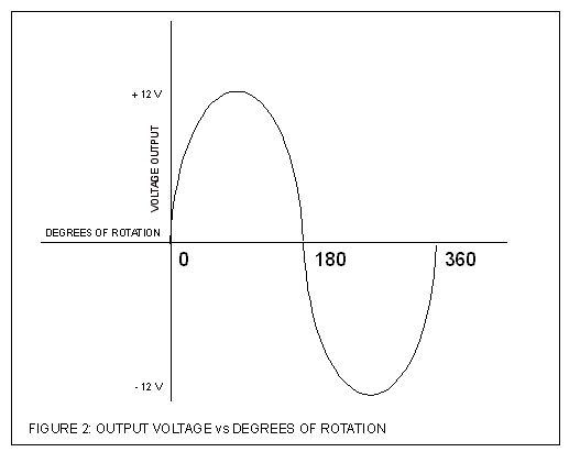
Image 002
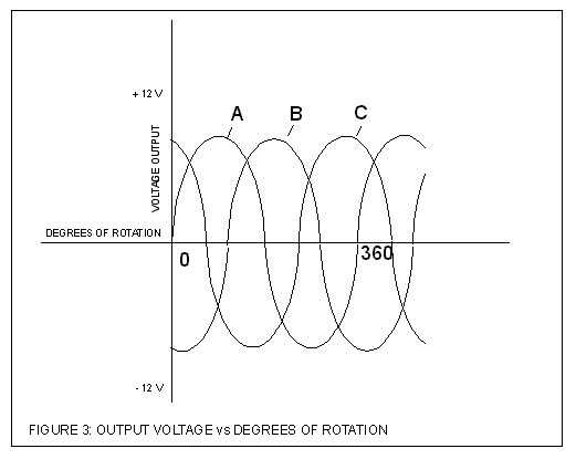
Image 003
These overlapping sine waves have their negative going voltages blocked off by
diodes, and thus we end up with a series positive humps of DC voltage. This is
referred to as a full wave bridge rectifier, as you can see in the below image.
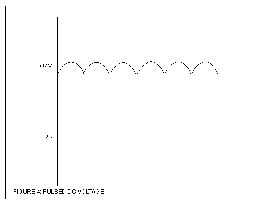
Image 004
We are generating the AC voltage needed, in order to rectify or alter it, to
produce a voltage and a current that is sufficient to charge the vehicles
battery.
The alternator is a three-phase generator with a built-in rectifier circuit
consisting of six diodes in a full-wave bridge rectifier circuit. The DC
voltage and current from the battery is supplied to the Rotor through the use
of slip rings mounted on the pulley shaft.
In essence the diodes are solid-state switches with no moving parts, making
them maintenance-free, until a failure mode is encountered.
When they fail, they usually short, either totally or partially. Partial shorts
in diodes are referred to as “leaks”. Leaking diodes will allow charging of the
battery, and when the vehicle is left sitting for a period of time, like
overnight, the battery may discharge through the leaky diodes and not start in
the morning.
When the rectified DC from each of the three-phase windings is added together
or superimposed upon each other, the positive peaks overlap to produce a much
cleaner DC with much less ripple. Trust me when I tell you that the copper wire
used in the rotor and the stator are specifically selected for their intended
duties.
Lead-acid auto batteries last longer when charged with pure DC voltage with low
ripple. Three-phase windings were designed into alternators to produce DC of
great purity, at least within the monetary guidelines of getting a decent
return on investment.
As the alternator’s pulley is rotated by the alternator belt, (connected to the
automobile engine's crankshaft), the rotor is spun past a stationary set of
three-phase windings that make up the stator.
Recall that changing the magnetic field will change the induced voltage.
Automotive engineers take advantage of this fact by altering the field strength
of the alternator (rotor assembly) in order to correspondingly change the
output of the Stators’ rectified AC voltage.
Speaking of the rotor, you may be wondering how in the heck do we get reliable
electrical connection to a rotating assembly?
The engineering folks used a clever set of copper "rings"
incorporated into the shaft of the rotor assembly. Stationary “carbon
brushes" are held in firm contact with these “slip rings” by spring
pressure. This supplies the voltage (derived from a fully charged automotive
battery) required by the rotor assembly to create the magnetic field. The rotor
receives DC voltage and current, and the stator windings utilize the resultant
induced EMF to generate AC voltage and waveforms. The rectifier (full wave
bridge) converts the AC waveforms (all 3-phase’s) to a DC voltage and current
with a ripple voltage capping it. The regulator circuit helps smooth out this
DC charging voltage and current, which becomes the alternator’s output.
Many modern alternators are equipped with built-in "regulator"
circuits that automatically switch battery power on and off to the rotor coil
in order to regulate output voltage.
It is the regulator’s job to control all of this diode rectifying and
modulation of the field strength, in modern day alternators. Some regulators
are designed so that the field strength is such that it will not produce an
output in the stator windings until a minimal threshold level is overcome.
That is why some vehicles need to have the engines revved, so the alternator
“kicks in”. At idle, little or no alternator output is evident. Often,
complaints are voiced that do not take the engineering design parameters of
alternator design into consideration…”…my brand new 10-Zillion Watt Stereo
sounds like crap at idle…”
.
Delcotron 10-SI Series alternators.
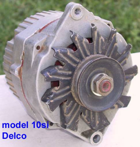
Image 005
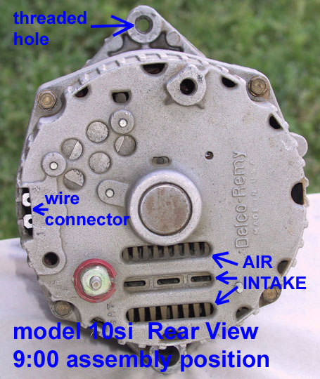
Image 006
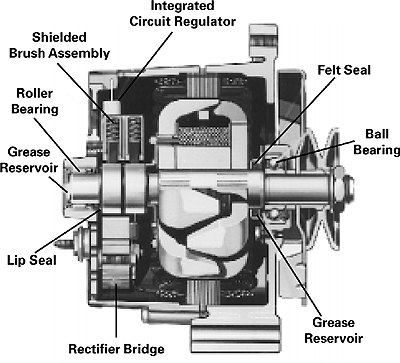
Image 007
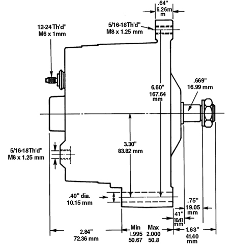
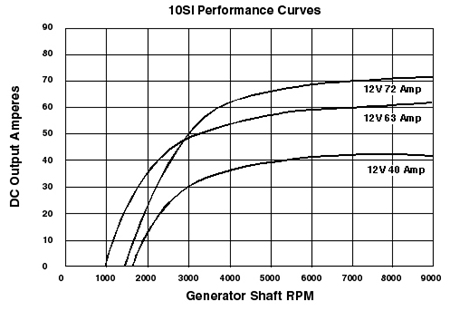
Image 009
14 amps at 2000 alternator rpm’s/40 amp model
.0 amps
at 1000 alternator rpm’s/63 amp model
35 amps at 2000 alternator rpm’s/63 amp model
48 amps at 3000 alternator rpm’s/63 amp model
53 amps at 4000 alternator rpm’s/63 amp model
Amp’s/RPM’s of 72 Amp unit
.0 amps at 1500 alternator rpm’s/72 amp model
23 amps at 2000 alternator rpm’s/72 amp model
50 amps at 3000 alternator rpm’s/72 amp model
62 amps at 4000 alternator rpm’s/72 amp model
"1"- this terminal (usually closest to the "Bat-terminal")
is fed from the Ignition thru a lamp ("idiot light"), and is used to
supply the magnetic field inside the alternator with the voltage needed to
operate. When the engine is running, if the idiot light is on, the output
voltage of the alternator is out of specification. Some vehicles utilized a
resistor wire of 15.6 Ohms in lieu of the lamp to drop the voltage at this
terminal to specified levels (this may be regulator specific).
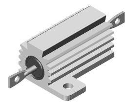
RH-50
This increase in voltage eventually reaches a point (as the alternator charges
the battery) to where it is equal to the voltage divider circuit designed into
the alternators regulator. Thus they equalize out and the voltage being fed to
the "1"-Terminal during normal vehicle operations the lamp only
lights when there is an over-voltage or under-voltage condition.
The “idiot” light is there to act as a “visual enunciators” under voltage and
over voltage conditions at the battery. Either of these conditions will
energize the "idiot" light.
"2"- this terminal can be fed from the positive battery post or the
starter solenoid where the positive battery post connects to the solenoid
switch. This is an input to the alternator that is used to sense the battery
voltage; some applications use a modified regulator circuit and may only use
one or even perhaps neither of these two regulator terminals. One-wire
alternators come to mind here.
That is about all there is to it, in the most simplistic terms.
For a bit more on the regulator circuit itself, read on...this will get
technical in nature, so go ahead and skip on down (to Section Three), if your
eyes begin to glaze over.
Image 010
The voltage divider (R2/R3) supplies a reference voltage to Zener diode (D2),
which is now “Off”, and thus blocks any voltage so that there is no forward
bias on the base to emitter junction of the NPN Transistor TR2, therefore it
cannot conduct. This results in the emitter of TR2 being pulled “High”. So now
base drive can be applied to TR1.
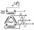
Image 012
This happens over and over...energizing and collapsing the magnetic field
thereby controlling the alternator output, it is a wonder that these
alternators last as long as they do.
Delcotron 12-SI with 6 cooling air intakes…these were available in
56-amps, 66-amps, 78-amps, and 94-amps.
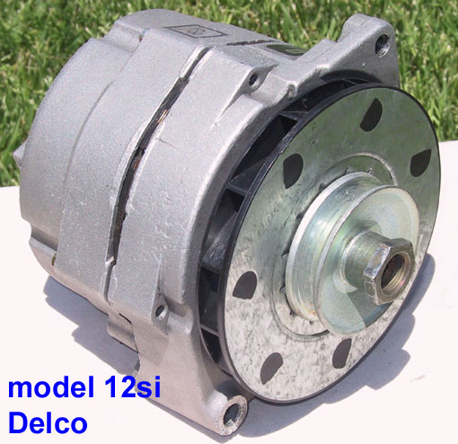
Image 013
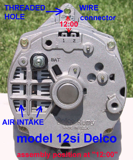
Image 014
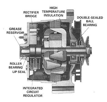
Image 015
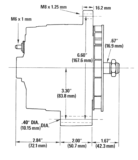
Image 016
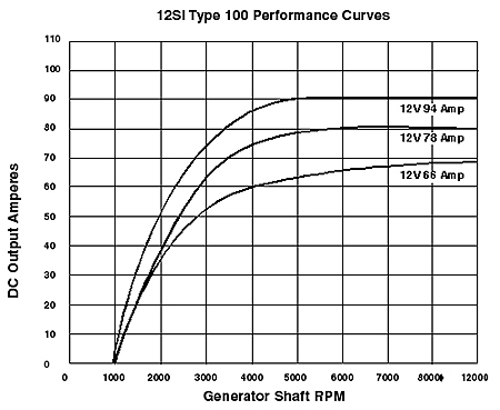
Image 017
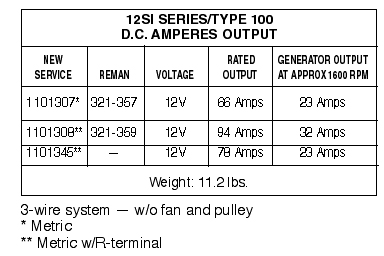
Image 018
Section 3…”The CS-130, CS-130D and
CS-144…now referred to as “Generators” by Delco!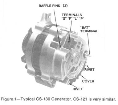
Image 020
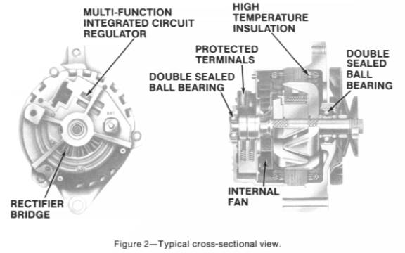
Image 022
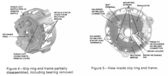
Image 024
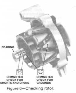
Image 026
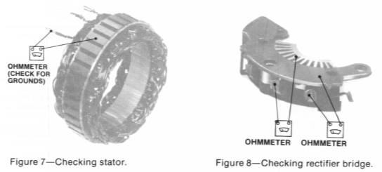
Image 28
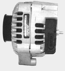
Image 030
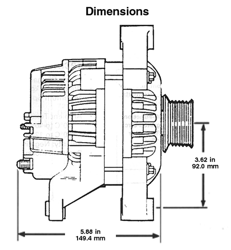
Image 031
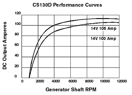
Image 032
http://www.acdelcotechconnect.com/pdf/tas_alt_clock_cs.pdf
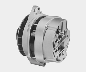
Image 033
CS-144
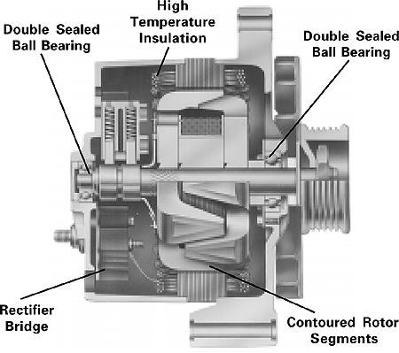
Image 034
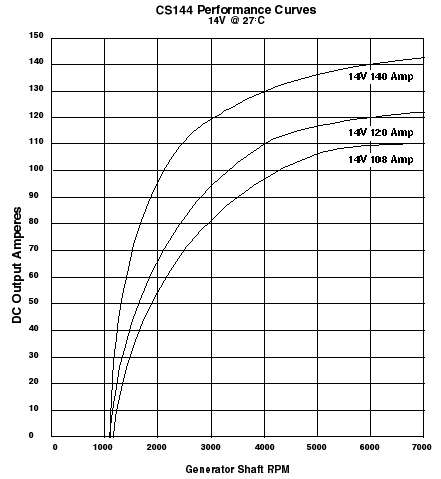
Image 035
I happen to like the CS D-series of Delco alternators. A quick note is
warranted here, the Delco CS-130 regulators are “smarter” than the previous
designs, and incorporate an under-voltage detection scheme built into the
regulators. This means that the alternators may not “turn on” if the “sense”
circuit detects a battery voltage substantially less than 12Vdc, unlike the
earlier 10-SI and 12-SI regulators. This is not an iron clad rule as there are
various setups regarding wiring the CS-130 alternators into a vehicle, just
make sure that the battery you install is fully charged.
Image 036
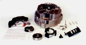
Image 038
Exclusive "Iceberg" Patented Finned Housing for Better Cooling
Heavy Duty Rectifier with 50 Amp Press Fit Diodes. (OEM rectifiers use only 35
amp diodes)
Copper Heat Transfer Grease for Better Rectifier Performance and Life.
10mm Wide Rear Bearing. (original uses only an 8mm bearing)
Brush holder Assembly
Bearing Tolerance Ring
Drive End Bearing with Retainer
Positive Battery Post Insulator
3 Stator Lead Extensions
Stator Lead Cover
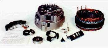
Image 040
Exclusive "Iceberg" Patented Finned Housing for Better Cooling
Heavy Duty Rectifier with 50 Amp Press Fit Diodes. (OEM rectifiers use only 35
amp diodes)
Copper Heat Transfer Grease for Better Rectifier Performance and Life.
10mm Wide Rear Bearing. (original uses only an 8mm bearing)
Brush holder Assembly
Bearing Tolerance Ring
Drive End Bearing with Retainer
Positive Battery Post Insulator
Plus-High out-put 140 Amp Stator (original CS-130 alternators come with 85-105
amp stator)
Stator Lead Cover.
The terminals on the CS130 series alternator also have a different design, as
depicted in the schematic diagram below.
Image 041
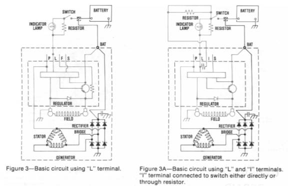
Image 043
Image 044
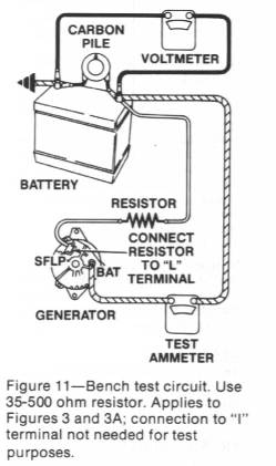
Image 046
Although testing via resistance and voltmeters can detect most variations, the
test set up is best left to a test bench. Again with all of the different
regulator circuits out there, some in-depth knowledge is required so that
damage to the regulator circuits do not occur, and there are a plethora of
designs out there, both OEM and especially after market.
Disconnect the PLI/FS voltage regulator connector before disconnecting the BAT terminal
Disconnect the BAT terminal last
The alternator is now ready to be removed
Install and secure the alternator with the mounting hardware
Attach the BAT terminal before connecting the PLI/FS voltage regulator connector
Attach the PLI/FS voltage regulator connector
Insure belts are tensioned properly and there is no interference with the alternators terminals
Connect the Negative Battery Cable.
P-Terminal: The Pulse/Phase terminal can provide a 12V square wave to determine
alternator speed, used by some Electronic Control Modules or vehicle computers.
Connects to the stator. Some ICU’s monitor this signal and adjust engine
parameters accordingly.
F/I-terminal: has several duties depending on the specific regulator, some
regulators have a resistor that is internally connected between the Field and
Lamp terminal. Other regulators use the F/I terminal to provide field duty
cycle information to the vehicles Electronic Control Module or computer. These
regulators are not interchangeable, but for our Jeeps, it hardly matters. For
ECM related vehicles it can be of paramount importance. If the alternator that
is selected comes from a vehicle that only uses the I-Terminal then the wiring
may simply require a wire from an ignition source in order for the alternator
to operate correctly.
S-terminal: This is a heavier gauge terminal spade lug that is connected to the battery. This terminal is the “Sense” circuit and monitors battery charge. The S-terminal on the CS-130 regulator is larger than the other three terminals.
Since these CS-series regulators are now essentially an electronic computer
chip, so always disconnect the battery before servicing, and do not EVER remove
the battery cable when the engine is running. If you simply must do this, you
may have just destroyed the regulator’s computer chip. You must really begin to
think of these alternators as computers, and treat them with the respect that
you might a laptop computer.
CS-Series alternators use diodes within the rectifier plate known as avalanche
diodes. Original equipment designs use avalanche diodes in both positive and
negative plates with a forward voltage of 0.9V @ 100 Amps and an avalanche
voltage of less than 40 volts, in the better-designed regulator/rectifier
units.
We don’t need to go into Epitaxial Planar Diode structure, just suffice it to
say that the OEM regulators and diodes are tested and function the best. Try to
stick with alternators that were rebuilt with OEM parts, you will generally get
a better quality rebuild.
Most of the CS regulators use Application Specific Integrated Circuits (ASIC).
And more to the point, Application Specific Voltage Regulator (ASVR) computer
designed chips, which may be encased in a plastic housing or a heat dissipating
enclosure of metallic structure. As a side note, Delco refers to their ASVR
regulators as All Silicon Voltage Regulators.
A word about aftermarket products and alternators purchased at some of the
lower tier automotive aftermarket outlets.
In the VAST majority of cases, the only things that go wrong on alternators are
the brushes wearing out (resulting in a weak magnetic field, this can be easily
checked by placing a screwdriver against the alternator case) or the internal
regulator/rectifier or diodes going bad. Unlike the 10-SI or 12-SI units,
repair of the CS-series alternators by the layman is not nearly as simple as it
used to be.
The diodes almost always short out or begin to “leak”, this is why many folks
first notice battery drains, and in the morning the vehicle does not start.
Avalanche diodes “collapse” and allow field current to continue to flow,
thereby continuing the alternator’s output, instead of shutting down (losing
forward bias) and starting up (overcoming forward bias thresholds) which
creates surges and spikes. These diodes eventually leak and allow a path to
ground, which eventually will drain the battery.
When the regulator goes, generally overcharging or undercharging are the
symptoms, and if you have the “L”-terminal connected to an interior lamp, the
lamp should begin to glow, giving you a fault indication. So, if the lamps
lights then look for an under voltage or over voltage symptom, or perhaps a
wiring fault.
The regulators may ship with new brush assemblies, and the regulator circuit is
mounted on a heat sink and can be replaced, most brush/regulator assemblies
cost under $40 dollars. These new regulators are built on surface mount
technologies on thick film hybrid electronics packaging utilizing third party
Computer Aided Design/Computer Aided Engineering designs, chip and wire welding
flip chips assembled on modern production lines, to shorten the period from
customer order, material control, manufacturing process, quality control and
customer delivery. (Customers in this particular sense are the aftermarket
suppliers to the rebuilding trade industry)
I will point out that unsoldering the lead connections of the stator field coil
wires can be “problematic” (PITA) if not done correctly.
Otherwise that is all that generally needs to be replaced when overhauling
these units, the regulator and the brushes. About $40 dollars, tops, and your
time and skill to remove, disassemble, repair, re-assemble and reinstall the
unit.
Well, there is my rant on the subject…
Image 047
So, getting back to our junkyard alternators, pull the alternator and on the
way home, stop at any Auto Parts store and have them check it out on a test
stand. After the unit is found to be good, buy an appropriate connector to plug
into the back of the alternator, don’t forget this little detail, or back to
the store you go!
The pulley will have to be changed, as most of the Chevy/GMC products use a
serpentine belt, most FSJ’s use a V-belt.
Anyone with an impact wrench (tire change shop or garage that fixes flats) can
do this for you, just stop by and offer a dollar for the greasest/natiest
clothed guy there to remove it for you, I have never been turned down,
especially if you time it just before lunch… timing is everything… eh?
Take the front cover off, and using your old alternator as a pattern to refer
to, "re-clock" the front housing so that the alternators rear plug in
harness will be in the same orientation as your old alternator, and the
mounting holes line up the same as the old alternator. Additionally. Ensure
that the Plug Housing and the Generator output threaded post do not place the
associated wiring in close proximity to your exhaust manifold.
Image 048
By re-clock I mean that the two piece housing can be pulled apart, and the
pulley side of the housing can be turned either clockwise or counterclockwise
in order to ensure that the mounting hardware and the back plug are oriented
the same way as the old alternator, which allows you to plug in the harnesses
and connect the output of the alternator so that no shorts, or excessive
heating occurs as might be the case if the wire harnesses were allowed to
connect to the exhaust manifolds.
Otherwise the plug in harness may go up against the exhaust manifold...not
good, and the tensioning bolt hole will not be in the right spot, also not
good.
Ok, go back to another tire place (or the same one) and get the pulley
installed on the CS130-series or CS-144 alternator that is your cool new toy.
(A touch of Lok-Tite on the threads will insure secure mounting)
You are ready to install, total out of expense so far should be about $30
dollars.
The BATT goes directly to the solenoid post that connects directly to the
positive battery post.
The "L"-Terminal can be used to supply the voltage "sense"
to turn on the alternator. On the older FSJ’s there was a wire resistor feed to
Terminal No. 1 on the 10/12-SI units, this could serve. A better choice would
be to mount a light in the cab, and connect its high side to a switched 12Vdc
source from the Ignition Switch and the low side to Terminal No. 1… wait a
minute…there is already such a wire in the harness, the resistor wire. So
replace it with a better insulated resistor wire, and that takes care of the
L-Terminal pigtail on the new connector.
The CS130D and CS144 alternators are an improvement on the CS130's.
Summit also has kits for Jeeps, and there are other vendors who will supply you
with everything and install it all for about $150 dollars.
Any alternator/rebuild shop can get it done so ask them to install an OEM DELCO
ASVR!
Now please understand that I skipped over just about a bazillion technical
issues on this post, but it will give you a general idea of the charging
systems on these old FSJ's, and yeah, I know my wiring instructions are pretty
sketchy, so many details…so little time. Jeep FSJ’s were made from the 70’s to
the 90’s and there are variations in the wiring. Additionally, there are other
items to consider, such as the conversion plugs for SI-to-CS and which CS-Series
alternators is the best for your particular application.