This is an article by Joe
Guilbeau on alternators & alternator theory for those
used in our FSJ's.
(Depending on your connection speed, this may take a short while to load due to
the number of graphics in the page).
10/28/2010 Version 17 rev. 1
Click here to return to Oljeep.com
Index
of Section Topics…
Testing your charging system with a voltmeter
Electrical flow thru conductors
Magnetism and induced voltage and current
Electromotive Force (EMF) and its role in Alternators
Rotor, Stators and their roles in Alternators
Basic overview of the
alternator and how voltage and amperage are generated
Section 2…”Delco 10-SI and Delco 12-SI
Alternators used in our Jeep applications”
Delco 10-SI external front and back photos
Delco 10-SI internal cut away view
Delco 10-SI Amps vs. RPM Chart
Delco 10-SI Electrical connections
Dale Vishay RH-50 16-Ohm Power Resistor to replace
your existing resistor wire
Delco 10-SI and 12-SI Regulator Circuit diagram and
circuit theory
Delco 12-SI external front and
back images
Delco 12-SI internal cut away view
Delco 12-SI Amps vs. RPM Chart
Section 3…”The CS-130, CS-130D and CS-144”
Delco CS-130 Front and side views
Delco CS-130 internal cut away
views
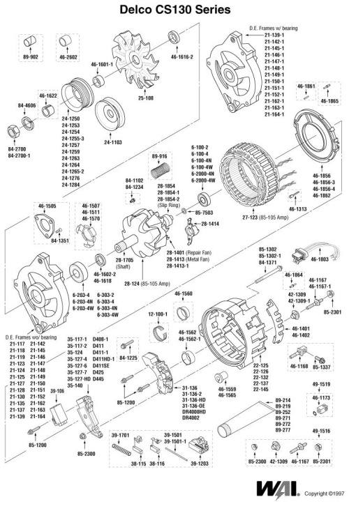
Delco CS-130 Exploded parts diagram
Delco_CS_130D_external_dimensions
Delco CS-130D Amps vs. RPM
Chart
Delco CS-144 internal cut away
view
Delco_CS_144_Exploded_parts_diagram
Delco CS-144 Amps vs. RPM Chart
Iceberg Upgrade Kits for the
CS-130
Delco CS-series Regulator/Rectifier
Voltage divider circuit to
fine-tune Voltage Regulators
Section 4…”Some practical
upgrades for the do it yourselves (DIY)”
Delco CS-Series Alternators Installation and Removal
Serpentine Pulley Kit from
BullTear
Delco SI-CS Wiring harness plugs
Section 5…“How to Guide” upgrades for
you penny pinchers out there…”
Instrument cluster from 1963

Image 001 is courtesy of Jubilee Jeeps jubileejeeps.org/tech/fsjcluster.htm
Section 1…“Alternators 101” Return
One may easily determine
the health of the charging system by simply taking voltage measurements on the
battery. When the vehicle has been sitting, say overnight for those who work
during the days, one can take a measurement with a voltmeter by setting the
meter to measure DC Volts in the 20Vdc position. Some meters are auto, so this
might not apply to those who have these style meters. Before you start the
vehicle, take a measurement across the battery terminals, it should be
somewhere between 12.5Vdc - 12.75Vdc, depending on the regulator circuit you
have inside your particular alternator.
While you are there, take two measurements... one across the
battery posts without touching the battery cable terminals, and a second
measurement on the battery cable terminals themselves. If your connections to
the battery are good, then the voltage readings will be almost exactly the
same. If there were one or more volts difference, then the battery cables are
not making the optimum connections to the battery post. This will interfere
with accepting a charge and interfere with the batteries capacity to deliver a
voltage and current to vehicle loads.
Another simple test is to turn on the AC, Lights (in other
words put a load on the alternator) and do a voltage test from the Positive
battery post to the Bat or B+ terminal on the alternator. You should read below
0.5Vdc, if your reading is significantly higher, there might be connection
problems between the alternator and the battery. The reason for putting a load
on the alternator is to insure that it is charging and this is the condition
that we are most interested, since the more amps, the greater the voltage drop
will be across the cables.
Do the same test on the Negative battery post to the case of
the alternator, you should read less than 0.3Vdc, if not then check the wiring.
If the above test ok, then turn off the engine and turn on
the headlights for about 10 seconds, this drains off the battery to give a
truer reading, it has to do with the surface charge that the battery gains by
charging. Take a voltage measurement across the battery terminals, we want
12.5Vdc or greater. If you read less than 12Vdc, something around 10Vdc; then
definitely take out the battery and charge it at an auto parts store, this is
free. After they charge the battery, have them perform a load test on it.
So now, we have a fully charged battery, we know that it
along with the wiring, and cabling is good. When the vehicle is started, the
alternator should put a minimum of 13.5Vdc to the battery, but no more than
15.5Vdc.
A voltage measurement of 13.5Vdc or less indicates that your
pulley belt might not be in good shape or is no longer tensioned properly.
Usually we want less than ½-inch of deflection on the belt, not too tight!
Re-check it after 20 minutes of driving.
If, after running and tensioning the belt you still read less
than 13.5Vdc, your alternator is undercharging. If you have an internal
regulator, your alternator is most likely in need of servicing. For those of
you with external regulators the alternator is receiving bad information, or
has failed. Another possibility is that the wiring is not correct to the
regulator and the alternator is not receiving what it needs in order to control
the charge.
The alternator might have a failed circuit, and thus will be
unable to deliver a proper charge to the battery. If the battery is almost
dead, and there has been some work done on the vehicle, then examine the
connections to the regulator. For instance, switching the regulator connections
on a SI-Series alternator will result in a discharged battery, this is because
the battery voltage that the No. 2 terminal requires in order to energize the
rotor field windings is no longer coming from an Ignition switched supply. If
this is the case, say after a wiring harness retrofit, then the regulator will
be giving power to the regulators resistive voltage divider that is always
connected to ground and therefore the battery will simply discharge through the
regulator.
So, pull the plug off the regulator on the alternator (the
2-pin Molex connector) and take a measurement from the No. 2 terminal to
ground. With the ignition in the "Off" position, there should be no
voltage present, if there is; then something is wrong with the wiring.
Sometimes when work has been done on the harness, the two wires on the
SI-series Molex connector are switched, and the battery is draining thru the
regulator circuit.
If unplugging the Molex connector on the regulator circuit
stops the battery from discharging, and the wiring on the harness side of the
Molex connector is right, then it is a good bet that the diodes inside the
alternator (either the diode trio or the rectifier diodes) are damaged and are
leaking, providing a path for current to flow to ground and thus draining the
vehicle while it sits at rest.
Taking the alternator in to a parts house may not catch this
problem, as some machines will simply test to see if the alternator will output
a charge, a better machine would detect this problem, so be sure to ask the
parts folks, if they don't know, then go ahead and ask for another alternator,
especially if yours has a lifetime warranty (highly recommended).
The rectifier circuits in our alternators are the Number One
failure mode for these alternators.
When you get yours rebuilt go for a Transpo DR5042 rectifier
for the SI-series. These are heavy-duty rectifiers with six 50-amp button
diodes and a beefed up heat sink that allows for cooling air to circulate
underneath the diodes. Since the 10-SI alternators pull air from the rear of
the case, up against the exhaust manifold; they need all the help they can get.
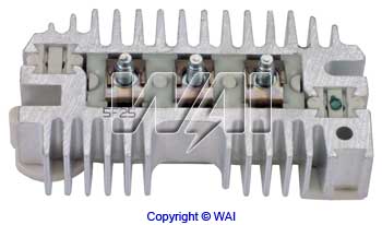
Image 002 Rectifier http://search.waiglobal.com/partnum.aspx?part=DR5042
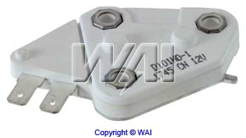
Image 003 Regulator http://search.waiglobal.com/partsearch/partnum.aspx?part=D101HD
Transpo D101HD is a Heavy Duty regulator for the 10-SI units
as shown above. It has a 5-amp rotor field winding feed and a 14.8Vdc set
voltage, good for the 12-SI as well.
If you understand or don't care about the electrical
characteristics of how magnetism is created in field windings and harnessed for
use in alternators, please go ahead and skip this next portion, and move on to
“Section 2”.
Return Otherwise, read on for a
brief discussion of what is happening in the world of electricity, electronics
and regulators, rotors, stators, field magnetism, diodes and how it all comes
together to keep our FSJ’s electrical systems all squared away. This is not
very technical and is generic, to boot. By the way, even the best minds in
science do not know what electricity REALLY IS, what we do know is how to
harness it, but nobody really can tell you what “it” is. http://www.youtube.com/watch?v=BWyTxCsIXE4
For those of you who prefer visual enunciation I have
included a video that does a good job of educating the public on the basics of
alternators and how they work. This fellow is posting from
http://www.youtube.com/watch?v=0VzvhfI4UpA
Again, for those of you with a visual slant, here is a MIT
Professor (Walter Lewin, what a fine example of a human being!) lecture on the
subject matter. It is 50 minutes and covers a good deal on the subject matter
exposing the nuances of the electromotive force, electricity, and magnetism.
http://www.youtube.com/watch?v=qqkUeQ0nsF8
The beginning of the course can be found here…there are 37
lectures. He states that for educators it is not what you cover, but that it is
what you uncover that matters.
http://www.youtube.com/watch?v=yzFQhsq8SF4
Moreover, you can fast forward to the end of the series.
http://www.youtube.com/watch?v=faJ8RXQkk3o
We can quantify, measure, and harness it, but we are just
not positive what holds those annoying electrons and protons together, besides
some rather generic pontifications about valence shells or adjacent atoms
conduction bonds, energy bands, ionizations, down to quarks and on and on and
on… some of the latest theories include gravitrons and strings.
For instance, in the Conduction Band free electrons will
move towards a positive charge when a voltage (or heat) is applied across
something like silicon crystal. Evidently, electrons can only exist within
prescribed energy bands and as they gain enough energy, they can escape the energy
band that they occupy, and thus create a hole where they formerly resided.
This freedom of movement in the crystal structure we call
Electron Flow. In the Valence Shell, holes will be created when these same
electrons gain enough energy to escape from the Valence Shell and migrate to
the Conduction Band. While other Valence Shell electrons might not have enough
energy to escape the Valence Shell, they can and in many cases do have enough
energy to hop on over to that vacated hole (when an electron escapes a band by
absorbing enough energy, it leaves behind a hole that it filled while residing
inside that band).
We humans think that we are very clever (instead of superbly
rationalized) and theorize that a hole that was vacated by the electron, and
may now be occupied by another electron; which has absorbed enough energy to
move within the shell, but lacks sufficient energy to totally escape that shell
is now referred to as Hole Current. In all honesty, it is all just the same
process, however distinctions help one to visualize specific activities.
Return
When an electric current is passed through a conductor, a magnetic field is
generated which surrounds that conductor. The reverse is also true, in which a
conductor which moves within a magnetic field develops a current and therefore
a voltage potential on its windings or wire conductors. Current will flow if a
complete electrical path to ground is provided. This electron flow is a
principle of Electromagnetic Induction (EMI), and is utilized as a method of
inducing current in a wire that is passing thru a magnetic field.
To further illustrate this physics principal, imagine two
bar magnets placed end to end, the North Pole on one magnet facing the South
Pole on the second magnet. You now have set up a magnetic field that is present
in the space between the two magnets.
Passing a length of wire through this space will “induce” a
voltage. This is termed (oddly enough) an “induced voltage”. How much induced
voltage is dependent on the length of the wire (wind that wire around a large
bobbin and you suddenly have a lot of wire) that is passing thru the magnetic
field, and the rate of speed that the wire achieves when passed through that
magnetic field. Additional wire would mean additional voltage, and therefore
additional current, all other things being equal (namely the magnetic fields
intensity in this case). If you increased the magnetic field strength, then the
voltage and current will increase proportionally.
The wire moving through the field may appear in different
configurations. It might be a straight wire, or perhaps a coil or loop of wire,
or even loops of wire. The longer the length of the wire that is passing
through the magnetic field, the greater the voltage induced on that wire.
An increase in the magnetic field, will also produces an
increase in the induced voltage. Also, the greater the speed at which the wire
moves thru the magnetic field, the greater the voltage that will be produced
(induced) within reason, this is why alternators develop higher amps as the
speed of the engine increases.
In general alternators are rated at their peak amperage
output as in 105 amps. This rating will be when engine rpm has reached
something like 4,000 to 5,000 rpm’s for the SI-series alternators and 6,000 to
8,000 rpm's for the CS-series alternators. I have included graphs of both
styles later in this article. Do not think that you will have 105 amps output
from your 105 amp rated alternator when you are cruising along at 20 mph.
It does not much matter if you move the wire or move the
magnetic field, both activities will generate a voltage. If the magnetic field
is increased, an increased current will be induced, if the magnetic field is
reduced, a reduced current will be induced.
As Scotty, the engineer of “Star Trek” fame was fond of
saying…”Ya cannot change the laws of physics... Captain!”
The magnetic field that is developed and which surrounds a
current-carrying conductor can be visualized as spreading in a radial pattern outward
from the conductor. Much like ripples of water when a stone is dropped into
water, however the “ripples” of a magnetic field need to complete their path,
and they always attempt to return to the magnetic structure from whence they
originated.
Now just as in magnets, like charges repel each other, and
unlike charges attract each other. Most of us have at one time or another
played with magnets, place them together one way and they "stick
together" try reversing one of the magnates 180-degrees and they now
"repel" one another.
Those magnetic lines repel each other, the stronger ones are
the ones nearest the magnetic poles, since they repel other lines of magnetic
force, other lines are moved further away, and so on and so forth. The magnetic
strength of a magnetic grows stronger as the distance to that magnetic is
decreased, and grows weaker as the distance to the magnetic is increased.
So, getting back to how all of this works, we find that as
we manipulate the speed, the distance, or the magnetic field strength applied
(to the rotor); the resulting induced voltage corresponds in a like fashion,
and in turn will induce a magnetic field within the stator windings (this is
where the alternator develops its volts and amps to charge the battery).
Make a fist with your right hand, and do a “thumbs up”, and
hold your fist in front of you, now extend your forefinger like you are
pointing at something, the forefinger and the thumb will be at a 90 degree
angle from each other. Now if you take your right middle finger and make a
90-degree angle with the forefinger, your middle finger will be pointing to the
left across the chest area.
Holding the fist in this orientation, and not moving the
position of the fingers and thumb, if you point your thumb in the direction
that the conductor is going to be moved thru the magnetic field, and the
forefinger in the North to South direction of the magnetic flux, the middle
finger will point in the direction that electron current will flow.
If we increase the magnetic field, then the conductor cuts
through an intensified field for a given distance traveled, thus increasing the
induced voltage. A stronger magnetic field has its lines of magnetic force more
tightly bound. Increasing the number of lines of magnetic force that are cut in
a given distance and time, increases the induced voltage.
The laws of physics (“… Aye, Captain!”) also indicate that
changing the angle of the conductor that is passed through a magnetic field
will influence the induced voltage.
A 90-degree angle has been shown to create the greatest
induced voltage. By 90-degrees, we are referring to perpendicular as, for
example, a knife slicing a bread loaf.
The further one deviates from this 90-degree angle, the
smaller the induced voltage. In an analogy of slicing that loaf of bread, if we
cut it at an angle, the knife has to travel longer to cut thru the same
vertical distance of the loaf, and transferring this bad analogy to the
alternator, magnetic lines of force can be cut at 90 degrees, and thus travel a
shorter distance in a given period of time. Thus, they cut more magnetic lines
of flux in a shorter period, thus generating increased voltages. Cutting that
loaf of bread at a greater angle cuts the same number of magnetic lines of
force, but the blade has to travel a greater distance, and takes a bit longer
to complete.
Another interesting physics property to note is that if we
reverse the conductor back and forth thru the magnetic field, the voltages that
are induced will reverse, and we will find that the induced voltages will be of
opposite polarities from each other.
One direction thru a magnetic field might induce a positive
voltage, and reversing that same conductor (the opposite way) thru the magnetic
field produces an induced voltage that is of the opposite polarity. Even though
there is no change in the conductor, or the magnetic field, only in the
direction of travel.
Therefore, reversing a conductor back and forth thru a
magnetic field causes voltages to be induced and the voltages will be of
opposite polarities of each other.
In review of these basics, we can state the following…The
greater the speed of a conductor that is moving thru a magnetic field then the
greater the induced voltage that will be generated. The longer the conductor then
the greater the induced voltage, that will be generated. The denser the
magnetic field then the greater the induced voltage. The closer to 90 degrees
that the conductor cuts across the magnetic lines then the greater the voltage.
Another way to put all this is to simply state that:
The induced voltage is directly proportional to the rate of
speed of the conductor that is passing through the magnetic lines of force, all
other things being equal.
In this sense, the rate of speed can also be tied to the number
of magnetic lines of force that the conductor passes thru in a given period.
Increasing the speed or length of the conductor or magnetic field strength will
all result in increasing the induced voltage.
The same can be said of the opposite, reduce any of the
properties mentioned, and the induced voltage will be reduced in direct
proportion.
Return An alternator has a
coil of wire wound around a Ferro-resonate material. In this manner, an electro
magnet is created, because DC current/voltage is applied to this coil, current
flows thru it, and they create a magnetic field. This magnetic field is
polarized, which simply means that it has a North Pole and a South Pole. This
is essentially the rotor, and as it rotates, its magnetic field cut the Stators
coil windings, by creating a whirling magnetic field. If you stop the current
from flowing thru the rotor windings, the magnetic field will collapse. In
fact, this is how the regulator controls the output of the alternator; it opens
up the ground path thru the rotor, thus preventing the current from passing
thru the rotor windings.
When a current-carrying wire is wound into a number of loops
to form a coil, the resulting magnetic field is the sum of all of the single
loop magnetic fields added together. Increase the loops making up the coil, and
you increase the magnetic field.
In review, the rotating core of an alternator has an iron
core, which is called an armature. This rotor or armature has copper wire
wrapped around it. Passing 12Vdc to this coil of wire, results in direct
current flow (when the regulator grounds one side of the rotor windings), which
in turn produces a magnetic field and magnetizes the iron core, thus making the
magnetic field denser.
The rotor is heavy and is supported in the alternator
housing via front and rear bearings that support a shaft. Outside the
alternator, a pulley is mounted on this shaft to engage the alternator belt,
which is driven by the pulley on the crankshaft. Newer designed Voltage Regulators
in alternators now use a Pulse Width Modulated square ware of 12Vdc of about
400Hz. As this pulsed square wave is turned on and off, the magnetic field
strength is modulated as well, influencing the magnetic field density and thus
controlling the voltage and amperage generated by the alternator.
The stator of the alternator is made up of three loops or
coils of wire that are mounted to the housing of the alternator, which are
stationary. The rotating magnetic field whirls through these coils of wires
inducing three alternating current waveforms. Now, since this rotating mass is
changing the angles of the field strength (magnetic field) as it rotates, the
induced voltage and the current that these stator loops carry vary accordingly.
Therefore, now we have a dense magnetic field and as the
engine speed of the vehicle increases, we can see how the density of that
magnetic field increases. As this magnetic field is rotated, an induced Electro Motive Force is created in the three
phase stator windings that are 120 degrees apart. Return
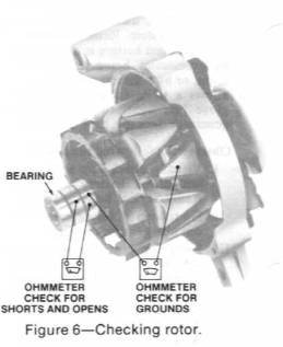
Here is a hint…want to know if the brushes on the alternator
need replacing, put a screwdriver against the alternator, being careful not to
get it hung up on anything, and check out the magnetism that the alternator
puts out. With experience and time, you can “feel” the difference in magnetic
intensity, and judge “good” brushes and “bad” brushes.
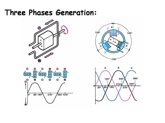
Image 004
In our alternator example, we have three loops of wire
(Image 004), and these three loops are placed such that a sine wave in each
loop is generated. A complete revolution of the rotor assembly, which is 360
degrees of revolution, gives us three overlapping voltages that are 120 degrees
apart (360 divided by 3 equals 120). Each stator loop coil creates a 360-degree
voltage that is known as a sine wave.
The induced voltage gradually increase until the angle is at
90 degrees (peak induced voltage and low current flow), and as the angle
continues to increase, the voltage (once at it's peak) begins to decrease
correspondingly (as the current increases); until the magnetic field begins to
approach another set of stator loops or coils of wire, and the process starts
all over for that particular loop coil, see Image 006 to visualize this
process.
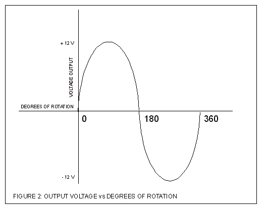
Image 005
The configuration of the windings (and associated diode
rectification configuration) causes these Alternating Current (AC) sine waves
to overlap each other, as depicted in Image 006 below and demonstrates how the
three AC waveforms are generated, on the left hand side of the illustration
notice that only one of the three rotor field magnets is depicted. The top left
image shows the stator winding and the arrows depict the current flow within
the stator field magnetic windings is shown, depicted also is the Rotator
spinning and it’s magnetic field North and South poles. Below it notice that
the illustration shows how one phase of the AC waveform is generated and the
relationship of the rotors field magnetism as the rotor spins. Notice the North
and South poles of the magnet.
Return On the upper right of this
illustration one and view the depiction of the stator windings, there are three
of them spaced 120-degrees apart from each other. Their waveforms as they might
appear on an oscilloscope are shown in the lower right hand section, the
waveforms lag each other by 120-degrees.
Return
 Image
006 By JTECHSAFF http://i58.photobucket.com/albums/g280/JTECHSAFF/Slide12-2.gif
Image
006 By JTECHSAFF http://i58.photobucket.com/albums/g280/JTECHSAFF/Slide12-2.gif
Once the AC voltages are created, we need to modify them
because our Jeeps run on 12Vdc. The battery is responsible for supplying power
to the electrical loads, and the alternator is responsible for keeping the
charge rate of the battery within design limits. There have been some
misconceptions on this matter, as some believe it is the alternator's job to
supply vehicle loads with the voltage and currents required. While it might not
seem obvious, it is actually the battery's job to supply any load, and it is
the alternator's job to keep the battery topped up and maintained at a proper
charge. The alternator will top off the battery if it senses that the battery
has been depleted, the battery is mindless and will attempt to supply any load
(up to and including a short to ground) with whatever is connected to it, while
the alternator monitors a point in the wiring harness to determine whether the
battery requires charging.
So overall, in most instances a larger battery capacity and
increased cold cranking amps are usually a better option. The American Wire
Gauge (AWG) of our Jeep harnesses were never designed to carry the current
necessary to fully charge a battery that has been severely discharged. Take
that battery out of the vehicle and charge it at home, or call a parts house to
use theirs, this is critical for those with ammeters in their Jeeps, as the
current must travel to the dash, thru the ammeter and then back to the battery
before any charging takes place. This puts an unacceptable burden on these old
wiring harnesses, and will eventually burn up your Jeep.
Returning to the waveforms, the overlapping sine waves have
their negative going voltages blocked off by the rectifier diodes, and thus we
end up with a series of positive DC voltages that are the sums of the three
stator coil voltages strung together. This is referred to as full wave bridge
rectified, as you can see in Image 007 below.
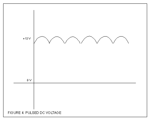 Image 007
Electronic components in the regulator circuits smooth out
this voltage, in order to generate the 13.5Vdc to 14.8Vdc required by the
battery for topping off and maintaining its charge. The various regulators
associated with alternators are responsible for this engineering task. Note
that it is actually the regulators that determine charge rates, voltage rates,
and how and when the alternator supplies the battery with voltage and current.
These voltage regulators generally charge the battery in the range of 13.5Vdc
thru 14.8Vdc, and the stator windings generally determine the maximum amperage
the alternator will supply. The simplified regulator circuits depicted in this
article do not show the filter circuits.
Thus, we see that the newer alternators (CS-series) are
three-phase generators with a built-in bridge rectifier circuit consisting of
six diodes. The DC voltage and current required by that alternator to operate
comes from the battery and is supplied to the Rotor using slip rings mounted on
the alternator's pulley shaft.
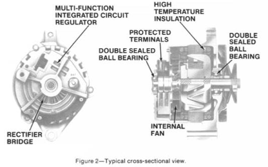
Image 010 gives a good cut away view of the slip rings and
the spring loaded brushes, look just to the right of the double sealed ball
bearing and you will see the two slip rings on the shaft with the spring loaded
brush assemblies just above them.
In essence, the rectifier bridge diodes are solid-state
switches with no moving parts, making them maintenance free, until a failure
mode is encountered. They allow current to flow when they are forward biased,
and no current is allowed to flow when they are reversed biased. These are
ideal, circuit theory statements. In actuality, some leakage current is usually
present when the diodes are reversed biased.
When they fail, they usually short, either totally or
partially. Partial shorts in diodes are referred to as “leaks”. Leaking bridge
rectifier diodes will allow charging of the battery, and when the vehicle is
left sitting for a period of time (as in overnight), the battery may discharge
through those leaky diodes so that the vehicle will not start in the morning. A
total short can cause an open circuit within the diode itself; it essentially
burns itself through although this is rare.
When the rectified DC from each of the three-phase windings
is added together, the positive peaks overlap to produce a much cleaner DC with
much less ripple. Trust me when I tell you that the copper wire used in the
rotor and the stator are specifically selected for their intended duties. That
is the wire used has been specifically developed generate cleaner voltages with
reduced spikes. Lead-acid auto batteries last longer when charged with pure DC
voltage with low ripple. Those three-phase windings were designed into alternators
to produce DC of great purity, at least within the monetary guidelines of
getting a decent return on investment.
Speaking of Rotors and Stators, here is a simple trick that
helped me distinguish them from each other.
Rotor… rotate
Stator…stationary
As the alternators pulley is rotated by the alternator belt,
(connected to the automobile engine's crankshaft pulley), the rotor is spun
past a stationary set of three-phase windings that make up the stator, inside
the alternator.
Recall that changing the magnetic field will change the
induced voltage. Automotive engineers take advantage of this fact by altering
the field strength of the alternator (the rotor field winding assembly) in
order to alter the voltage induced on the Stator windings resulting rectified
AC voltage (in the CS-series recall the pulsed width modified voltage applied
to the rotor windings, in the case of the SI-series alternators TR2 inside the
regulator opens and closes acting as a On/Off switch on the ground side of the
rotor coil).
Speaking of the rotor, you may be wondering how in the heck
do we get reliable electrical connections to a rotating assembly.
The engineering folks used a clever set of copper
"rings" incorporated into the shaft of the rotor assembly. Stationary
“carbon brushes" are held in firm contact with these “slip rings” by
spring pressure. This supplies the voltage (derived from a fully charged
automotive battery) required by the rotor assembly to create the magnetic
field. The rotor receives DC voltage and current, and the stator windings
utilize the resultant induced EMF to generate AC voltage and waveforms. The
bridge rectifier diodes convert the AC waveforms (all 3-phases) to a DC voltage
and current with a ripple voltage capping it. The regulators filter circuit
helps smooth out this DC charging voltage and current, which becomes the
alternator's output.
If it seems that I am being redundant in much of the
operation theory, please bear with me. It has been my experience that
presenting the material respectively and in various aspects will effectively
reach the greatest majority of the readers who may not have the in depth
knowledge that some others might posses.
It is the regulator's job to control all of this rectifying
and modulation of the field strength. Some regulators are designed so that it
will not produce an output in the stator windings until a minimal threshold
level (of the rotor magnetism) is overcome. Since the vehicles alternator rotor
must rotate in order to function, we find that a certain engine RPM must be
achieved so that the alternator can output a charge.
This is why some vehicles need to have the engines revved,
so the alternator “kicks in”. At idle, little or no alternator output is
evident, unless the engine throttle has been "blipped" in order to
energize the field windings (these are the rotor's windings) inside the
alternator. Often, complaints are voiced that do not take the engineering
design parameters of alternator design into consideration”…my brand new
10-Zillion Watt Stereo sounds like crap at idle…” In this particular instance,
a different regulator for the alternator is called for, one that generates a
charge at a lower engine RPM.
One of the other rather “odd” situations out there revolves
around some “OEM Regulators”; early on, it seems that the automotive battery
could discharge thru the regulator/ignition switch when the ignition switch was
turned off and the points happened to be closed (originally experienced on
older tractors). This provided a leakage path to drain the battery and in an
automotive application; this could take a month or so. The tractor guys brought
this “feature” to light, a battery in an auto is likely to be started at least
once a month, and as such, this parasitic draw was not very noticeable.
Now, lets get on with some technical details on FSJ
alternators…
Return
Section 2…”Delco 10-SI and Delco 12-SI Alternators used in our Jeep
applications”
Delco 10-SI Series alternators.
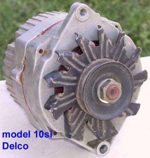
Image 008
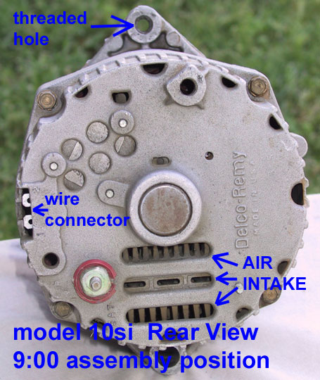
Image 009
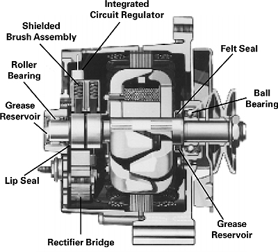
Image10 Return
Image 011 Return
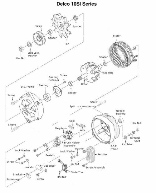
Image 012 Return
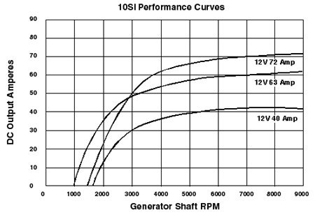
Image 013 Return
These were the 1st generation of Delco/Remy System Integral
(“SI”) alternators, meaning that the regulator was mounted inside the
alternator, instead of being a separate unit on the firewall or fender well,
and began showing up in the very early 70’s in GM products and weighing in at
about 10.5 lbs. This becomes quite a handful when replacing in some vehicle
applications.
With all Jeep OEM components installed they had outputs of
37-amp, 42-amp, 55-amp, 63-amp, 70-amp, and 85-amp, and finally a 94-amp
(according to my ’83 TSM) ratings, outputs higher than 100 amps can be
purchased but the heat dissipation and cooling requirements needed are just not
incorporated into these units, therefore most of these higher output
conversions are simply not recommended.
Cooling is accomplished via three vertical slots on the rear
housing and a pulley mounted cooling fan. The heated air from the passenger side
exhaust manifold is drawn into the housing. The threaded mounting hole and
orientation of the regulator connections determined the “clocking” of an
alternator, as depicted in Image 054.
Amps per RPM’s of 40 Amp units
0 amps at 1600 alternator rpm/40 amp model
14 amps at 2000 alternator rpm/40 amp model
30 amps at 3000 alternator rpm/40 amp model
36 amps at 4000 alternator rpm/40 amp model
Amps/RPM’s of 63 Amp units
0 amps at 1000 alternator rpm/63 amp model
35 amps at 2000 alternator rpm’s/63 amp model
48 amps at 3000 alternator rpm/63 amp model
53 amps at 4000 alternator rpm/63 amp model
Amps/RPM’s of 72 Amp units
0 amps at 1500 alternator rpm/72 amp model
23 amps at 2000 alternator rpm/72 amp model
50 amps at 3000 alternator rpm/72 amp model
62 amps at 4000 alternator rpm/72 amp model
Delco
SI-series internally regulated alternator have the following connections. One
large threaded stud that is the Alternator output, known as the Bat, this
connection has "Bat" cast into the housing (aftermarket housings may
not incorporate these marking. Return
In Image 009, one may see the threaded lug just to the left
of the three cooling intake slots. Two additional tabs (inputs to the internal
regulator) are used to interface the vehicles wiring harness, these have
"1" and "2" cast into the housing next to them. A two
terminal Molex connector is generally used to connect the vehicle's wiring
harness to the regulator circuit.
Here are the details on the individual terminals:
"Bat"- this terminal is for the alternator's
output to the battery. On some jeeps, this output goes directly to the ammeter
inside the cab, and returns and has a fusible link in series somewhere along
the line. Later versions used a voltmeter, and this terminal is routed to the
solenoid stud that interfaces with the Pos-Terminal of the battery cables.
"1"- this terminal (closest to the
"Bat-terminal") is fed from an ignition switched circuit with earlier
Jeeps having a lamp circuit ("idiot light"). This terminal is used to
supply the rotor's magnetic field inside the alternator. If the idiot light is
on with the engine running then the output voltage of the alternator is out of
specification, either too high or too low. Most vehicles utilized a Ni-Chrome
resistor wire of 15.6 Ohms in addition to the lamp to drop the voltage at this
terminal to specified levels. If the owner upgrades to a CS-series alternator
then there are pigtail harnesses that use 350-ohms of resistance in the wiring
adapter.
Ni-chrome wire is difficult to connect to and it is getting
harder to find insulated versions of it, notably due to the fact that
traditional usage of Ni-chrome wire as heating elements such as those used for
cutting foam products do not need the insulated wire jacket. This type of wire
has a specified amount of resistance per foot. One could use 15-feet 7-inches
of Ni-chrome wire rated at 1 ohm per foot, just make sure that you measure the
resistance from the firewall to the 2-in Molex connector to insure that there
is about 15 ohms of resistance in the line (this is applicable only if you are
repairing the harness and using the SI-series of alternators).
Return What you may want is a
Vishay-Dale RH-50 series power resistor in 16-ohms (Image 014). It is an
aluminum heat sink encased environmentally sealed power resistor that can be
attached to a bulkhead (firewall) and your No. 1 terminal wire soldered and
heat shrink insulated to the termination lugs. Operating Temperature range is
(-) 55 C to (+) 250 C; the model number would be RH05016R00F.
RH050 is the standard 50-watt rated metal-housed bulkhead
mount, and is completely welded for total environmental protection to meet MIL-PRF-18546
as applicable.
16R00 is a 16-ohm resistance (R is the code for the decimal
point).
F is a tolerance of 1% on the resistance value.
A data sheet web site is available at:
http://www.vishay.com/docs/30201/30201.pdf
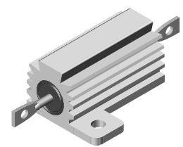
Image 014 Return
Quick simple and cheap, less than $10 dollars for one
shipped to your door. A distributor called Electrospec should have some in
stock, just go to the Electrospec website below and cut-n-paste or type the
part number into the Manufacture Part Number search bar, and you will get
information.
http://www.electrospec.com/account/rfqcart.asp
The lamp is in series with the rotor's "Field"
terminal, and this current limited voltage (in series with the 15.6-Ohm
resistor wire or Vishay Power Resistor) provides a reference voltage to the
regulator to start charging. Without correctly biasing the sense circuits
within the regulator, the alternator cannot operate correctly. When the
alternator begins to charge, the voltage increases at the battery. The “idiot”
light is there to act as a “visual enunciator” for under voltage and over
voltage conditions at the battery. Either of these conditions will energize the
"idiot" light.
"2"- This is an input to the alternator that is
used to sense the battery voltage; some applications use a modified regulator
circuit and may only use one or even perhaps neither of these two regulator
terminals. One-wire and self-energized alternators come to mind here. It
provides D2 (the Zener Diode) with a reference voltage. During charging, this
voltage has not reached the set point of the Zener and therefore the diode acts
to block voltage and current. When the battery acquires sufficient charge the
voltage at the Zener causes it to go into breakdown, thus current may now flow
thru the diode and thus the rotors groundside is now open and the magnetic
field no longer drives the stator to provide an output.
A word of caution here, if the No.2 Terminal is connected to
a non-switched voltage supply it will drain the battery, as it should be
connected to an ignition switched voltage source, the battery will drain
through the voltage divider network inside the regulator circuit. That is about
all there is to it, in the most simplistic terms.
Return For a bit more on the regulator circuit itself,
read on...this will get technical in nature, so go ahead and skip on down to
Section Three, if your eyes begin to glaze over.
 Image
015 Return
Image
015 Return
Refer to Image preferred voltage monitoring location, near
the splice in the wiring harness under the hood). If placed in this location,
it senses the charge condition of that point in the wiring harness, then routes
this voltage to a voltage divider network (R2/R3) with a capacitor (C1) in
parallel with R3 to filter it inside the regulator circuit. The resistance of
R3 is high. If it were a low resistance, the battery would lose its charge by
draining current thru that low resistance to ground. Recall that this is fed
directly from the battery and thus is always "hot". Therefore, R3 is
of sufficiently high enough resistance that it does its job as a voltage
divider, and yet does not drain the battery.
This voltage divider network limits the current discharge to
negligible amounts when the vehicle is not running. If your alternator has a
regulator that is charging the battery at 14.8Vdc, then go ahead and tie the
No. 2 terminal to the solenoid. If the charge rate is 13.8Vdc or so, then tie
the No. 2 terminal to the splice location in the harness which will, therefore,
give the harness a slightly voltage to deliver to the loads, and the alternator
will deliver a slightly higher charge to the battery. To check what voltage the
alternator charges the battery at, simply have someone rev the engine as you
take a voltage measurement across the battery terminal, at about 4,000 rpm’s
insure that the voltage across the battery does not go higher than 15Vdc.
In the charging mode, the circuit operates in the following
manner. The voltage divider (R2/R3) supplies a reference voltage to Zener diode
(D2). Zener diodes are generally silicon p/n junction devices that differ from
their diode rectifier counterparts. The Zener is designed to operate in the
reverse bias/breakdown mode. That is to say, when the Zener Diode has
sufficient voltage applied to it is then operates in the breakdown mode, the
voltage across the Zener diode remains essentially constant and the current can
flow through it. Therefore, it is essentially a voltage regulator, that allows
current to flow thru it.
The alternator starts and stops charging and resumes
charging constantly, many times per second. The alternator starts charging when
the voltage appearing on Terminal 2 drops to a specific level just below the
its breakdown voltage specification of the Zener Diode. The Zener no longer is
in breakdown mode, operates much like a rectifier diode, blocking voltage and
current, and is now “Off”. There no current available thru the Zener to forward
bias the base to emitter junction of the NPN Transistor TR2 and therefore it
cannot conduct. This results in the collector of TR2 no longer held at ground
potential, since the TR2 transistor collector to emitter junction is
essentially an open circuit, and not tied to a diode drop potential above
ground.
Therefore, the R1/D1 junction now has voltage applied to it
through Terminal 1 from the "Idiot Light" and ignition switch. This
means that base drive can now be applied to TR1 essentially closing the
collector to emitter "switch". This grounds the collector and the
anode of D3, making its anode more negative than its cathode that is tied to
Terminal 1.
The regulator circuit is now being fed from Terminal 1 that
provides base drive to TR1, thru R1 and D1. D3 is reversed biased and is
blocking current flow. With base drive, TR1 base to emitter junction is now
forward biased, and it acts like an “On/Off” switch. When it is on, as we are
currently examining, it provides a path for current to flow thru the rotors
field windings being supplied by TR1's emitter/collector junction to ground.
Therefore the alternator is charging at this point, because current is flowing
from the ignition switch thru the No. 1 Terminal on the alternator and TR1 is
"On" thus the rotor's field winding coil has voltage and current
being applied and these continue on thru the emitter/collector junction of TR1
to ground to complete the circuit.
The lamp circuit cannot supply enough current to the field
windings to sustain or generate the magnetic field in order to induce a voltage
output on the Stator windings. Therefore, in many applications the vehicles
engine must be revved to a higher RPM in order to generate enough initial field
strength so that the induced EMF is sufficient to self maintain it.
The Zener Diode D2 prevents current flow from Terminal No.2
from reaching the base of TR2. Return
The alternator is now charging the battery, and therefore
its voltage begins to rise. The voltage divider network (R2/R3 which is factory
adjusted) begins to see the voltage across R3 rising, in time; the alternator
charges the battery sufficiently so that the voltage rise across R3 reaches a
threshold. This threshold voltage forces Zener Diode (D2) into breakdown to and
biased into conduction, which in turn provides TR2 transistor with base drive.
Recall that the voltage should remain somewhat constant across Zener Diode D2.
Transistor’s TR2 base to emitter is now forward biased and
therefore its collector voltage is essentially “switched” to a diode drop
potential above ground. These turns off base drive to TR1 (whose base is now
held at about a 0.7Vdc potential) so it effectively “switches off” and no
longer provide a path for the rotor field current winding, and the rotor field
collapses. There is no longer any path for current flowing thru its coil to
return to ground, in effect TR1 becomes an "Open Switch".
Bringing the junction of R1 and the Cathode of D1 to a diode
drop potential above ground results in reverse biasing the cathode/anode
junction and therefore the Base to Emitter junction of TR1 is now reversed
biased and it no longer conducts and turns off.
The following diagram is a simplified representation that
illustrates the operation of the regulator circuit. The base drive controls the
“On/Off switching” of TR1… when the switch is on, the rotor coil current flows,
when the switch if off, no current flows in the rotor field winding, thus the
field collapses.

Image 016 Return
The alternator generates alternating voltage and current. A
diode trio rectifies the current that flows through the Q1 transistor, which
feeds the field windings of the rotor as depicted in Image 012, which happens
to depict a Delta configuration for the Stator Windings.
There also exists a Wye configuration and both are depicted
below in this image captured from the US Patent Office site for Patent #
7368839.[JAG1]
This happens repeatedly...energizing and collapsing the
magnetic field, many times per second, thereby controlling the alternator
output. It is a wonder that these alternators last as long as they do.
We will now discuss various aspects of the SI-series
designs. Each regulator circuit has its own designs and circuitry, which may
very well differ from the specific description above. The above example was
given to illustrate the basic operating principals of the regulator circuit,
and happens to be the circuit that is generally on the 10-SI and 12-SI units.
Since I am not privy to each regulator and rectifier circuit from 1963 to the
present, you will forgive me if the above description does not exactly match
the circuitry inside the alternators.
Concerning the maintenance of the 10-SI/12-SI alternators, I
would suggest Transpo Electronics as a supplier for your aftermarket source.
Regulators for the Delco 10-SI and the Delco 12-SI
alternators that I would suggest would be the D101HD. This unit is a heavy-duty
regulator, has a 14.8 Voltage set point, and provides a 5-amp field current to
provide the rotor with ample current. It replaces the following regulators;
Delco 1116387, 1116392, 1116423, D680, these regulators would be the stock
versions as originally shipped with Delco alternators.
Rectifiers for the Delco 10-SI alternators would be the
DR5042. This is a heavy-duty regulator designed for heavy duty Caterpillars and
farm equipment. Its components include 31-1401 Diode Lead, 31-1603 Terminal
Block and 32-735 Diodes, with 50A button diodes and an open base design for
better cooling & less dirt retention.
Brushes for the 10-SI would be the 38-104, and the 12-SI
would be the 38-106. links earlier in this article give web links and images of
the rectifier and regulator.
If your harness needs a replacement plug to the alternator
use the Transpo 46-1801, it is the Molex connector with pigtails. This is also
an extender of sorts that plugs into your existing harness and provides added
length if you (for whatever reason) need to re-clock your existing alternator
and its part number is 46-1869. These can also be found at better parts houses.
Delco 12-SI with 6 cooling air intakes…these were available
in 56-amps, 66-amps, 78-amps, and 94-amps.
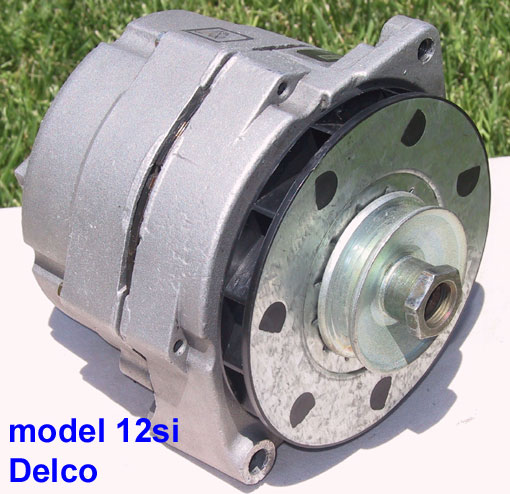
Image 017 Return
The cooling fan on a Delco 12-SI alternator is easy to spot,
as it is adjacent to the alternator pulley (the front of the alternators if you
will) and is a black thermoplastic with a metal plate attached between the fan
and the pulley for added strength. I am referring to the OEM alternators here.
These models began appearing around 1983. With under hood real estate becoming
a premium and greater electrical loads making demands on the alternators, the
12-SI with its increased cooling and higher output became a popular component.
Larger air intake ports on the rear of the alternator also contributed to
cooling.
These units can be purchased from aftermarket vendors with
outputs up to 140 amps. The interior and cooling components incorporated in
these units make this feasible. There is still the same heat issue that the
10-SI suffers from, namely that the cooling air that the fan draws from the
rear of the alternator is still backed up to the exhaust manifold on the
passenger side.
Just to reiterate the point, the cooling fan is draws air
from the back of the alternator (which is butted up against the engine and the
passenger side exhaust manifold) and pulls this heated air (from the rear of
the alternator past the rectifier heat sink towards the front housing), this
superheated air is now routed towards the front of the vehicle. As you can see
in the Image 018 below, the cooling vents are against the engine and exhaust
manifolds in our Jeeps, and the fan pulls this heated air thru the alternator
to “cool” its electronics
Recall that these vehicles started out in the early 1960's,
and if you were to look into the engine bays of these older vehicles, you will
notice that over the years, the real estate inside the engine bay became much
more cramped and thus the amount of cool air inside the engine bay has been
drastically reduced.
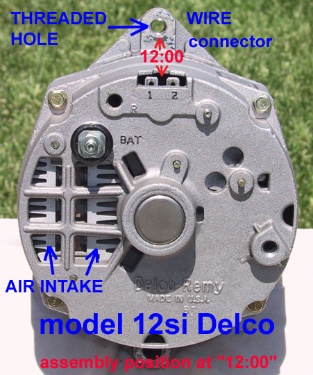
Image 018 Return
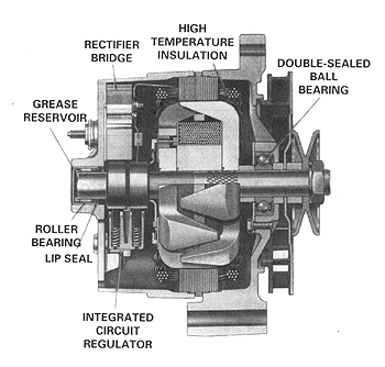
Image 019 Return
Image 020 Return
Image 021 Return
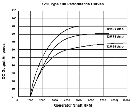
Image 022 Return
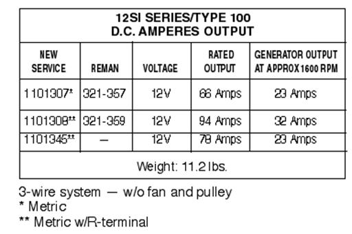
Image 023 Return
Improvements in the regulator circuit designs have occurred
but the operation is the same as in the 10-SI Series. These units are pretty
tough and usually give years of service.
Section 3…”The CS-130,
CS-130D and CS-144 Return
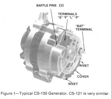
Image 024 Return
The
illustrations above depict typical CS-130 and CS-121 views. Return
Image 025 Return
Image 026 Return
Image
027 Return
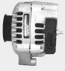
Image 028 Return
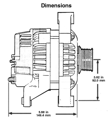
Image 029 Return
CS-130D
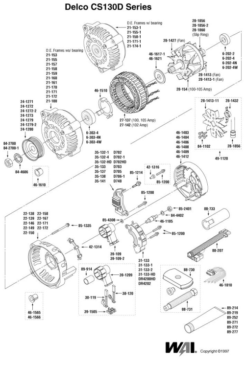
Image 030 Return
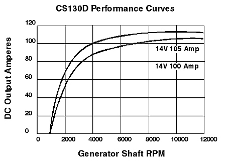
Image 031 Return
The rest of this post refers to the Delco CS units (CS-121,
CS-130 and CS-144) CS stands for Charging System and the 121, 130 or 144 number
behind a CS-*** refer to the outside diameter of the stator in millimeters.
This is essentially, why the CS-144 has a higher amperage capacity than the
relatively smaller CS-121 and CS-130 units.
The Delco CS-series alternators are supplied in 61-amps,
70-amps, 72-amps, 74-amps, 80-amps, 85-amps, 96-amps, 99-amps, 100-amps,
102-amps, 105-amps, 108-amps, 124-amps, 140-amps and 145-amp configurations.
The below URL link is a reference page that I pulled the
above information from. As I mention, there are many configurations. Just be
aware that there are many CS-Series regulators out there in re-manufactured
units, and as most re-manufactured units have a return on investment, many
parts houses put the cheapest components possible into their units. Let the
buyer beware and do a bit of research before blindly purchasing one.
http://www.acdelcotechconnect.com/pdf/tas_alt_clock_cs.pdf
Image 032 Return
CS-144
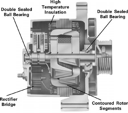
Image 033 Return
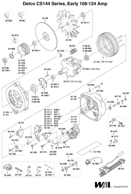
Image 034 Return
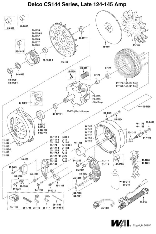
Image 035 Return
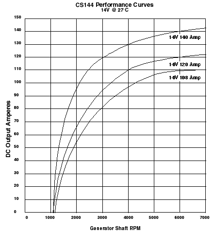
Image 036 Return
There are some good videos on the web that illustrate how
simple repairs to the Delco CS-144 alternators. I chose two in particular due
in part to the use of Transpo Rectifiers in the 1st Video, as well
as the fact that these are very well done videos.
Part 1 http://www.youtube.com/watch?v=riYZssdSmXY
Part 2 http://www.youtube.com/watch?v=vKbX7mezuFM
A Transpo Heavy Duty rectifier for the CS-144 early style
alternators is DR5176PF
For version w/ recessed Mtg. hole, use DR5178PF.
6-60A press-fit avalanche diodes
Crimp-weld diode connections
Heavy copper conductors
A Heavy Duty Transpo rectifier for the CS-144 late style
alternators is DR5180PF
For version w/ 70 amp, press-fit diodes use DR5180PF
6-70A press-fit avalanche diodes
Crimp-weld diode connections
Heavy copper conductors
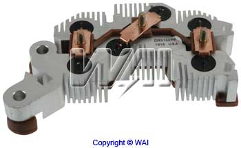
Image 037 Return
For those of you with an interest, a U.S. Patent Office
documentation for the CS-130 Bridge Rectifier is presented below. These
regulators are essentially computer chips now, and feature surface mount
technology and a host of other features.
I mention this so that the reader might conclude that one
may not treat these “regulators” in the same fashion as the earlier more
ruggedly designed regulators on the SI-series. The old adage of disconnection
the battery to see if the engine keeps running to troubleshoot the old SI-series
alternators will be an excellent way to ruin the CS-series regulators.
Page one of PATENTS 4,606,000 issued August 12, 1986
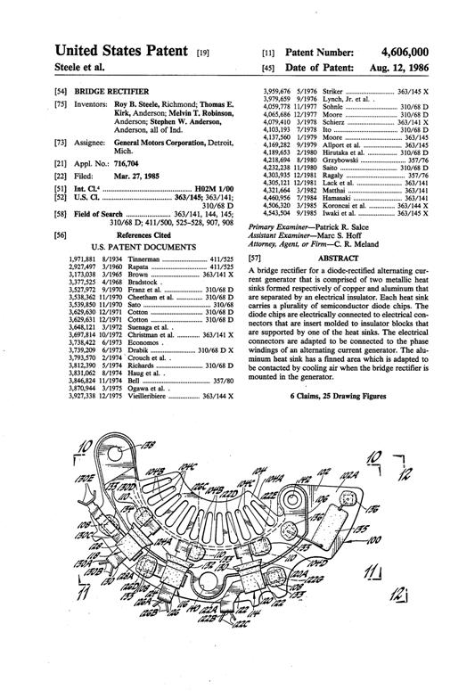
Image 038 Return
Bridge Rectifier for CS-130 generator
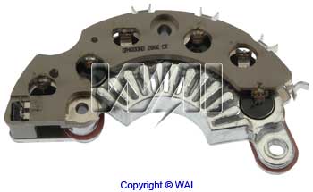
http://search.waiglobal.com/partnum.aspx?part=DR4000HD
A Transpo Heavy Duty rectifier for the CS-130 series
alternators is the DR4000HD with 50-amp press fit avalanche diodes, welded
diode terminals, high temperature lead frame, and the unit is Original
Equipment validated.
The below link will allow you to input the Patent number
“4,606,000” as a “search string”, in order to view the patent information
submitted to the US Patent Office. You may view pages 1-15 of the original
patent for the CS-130 Alternator and the Bridge Rectifier as granted on August
12th, 1986.
http://patft.uspto.gov/netahtml/PTO/srchnum.htm
The image 039 below is a patent that was applied for by
inventor Nicholas DeNardis for Transpo and centers on an improved rectifier
circuit for the Transpo CS-130 Rectifiers. The patent number is 6552908.
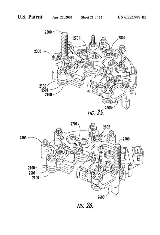
Image 039 Return
From the United States Patent
Office “…Our Web site provides full text for patents issued from 1976
to the present . We provide TIFF images for all
patents from 1790 to the present. You can search on text in
all elements (fields) of the patent or select those fields you wish to search
only for patents issued since 1976…”
You must have a reader in order to access the patent
information, the reader is free, go to the URL below to get the free reader,
after you choose the correct version for your computers Operating System, you
can load the free reader and take a look at the images that were filed as part
of the Patent process (Engineering Design Drawings, Mechanical CAD/CAM).
http://www.uspto.gov/patft/help/images.htm#not
I like patent info, some of the BS out there is incredible,
and a little research at the US Patents Office can shed some light on what is
real and what is hype. Aftermarket ignition systems come to mind here, I like
MSD!
For some preliminary information of the images, I have cut
and pasted the following from
the U.S. Patent site.
“…PTO's full-page images, nearly four terabytes overall, are
stored and delivered at full 300 dots per inch (DPI) resolution in an image
file format called "TIFF," using CCITT Group 4 compression. This is
the format, which is required by the international standards to which all
patent offices must conform. TIFF is also the most used image format in the
world. Unfortunately, due to the volume of the image data, available funding,
and other technical considerations, PTO cannot convert these images to a format
more popular on the Web either permanently or by converting on the fly as they
are delivered.
As a result, you must install and use a browser plug-in
similar to those required to access Adobe® PDF files, RealPlayer®, or Macromedia
Flash® files on your workstation in order to view these files directly. An
alternative method is to use third-party software or services to view these
images either directly or after conversion to another format, such as Adobe®
PDF.”
The plug-in you use cannot be just any TIFF image plug-in.
It must be able to specifically display TIFF files using ITU T.6 or CCITT Group
4 (G4) compression. The only free, unlimited time TIFF plug-ins offering
full-size, unimpeded patent viewing and printing unimpeded by any advertising
on Windows® x86 PCs of which we are aware are.”
Well, enough on the US Patent Office and Patents, after the
introduction of the CS-130, Delco modified the alternator and came up with the
CS-130D. This translates to a Charging System with a 130 mm diameter stator
with dual INTERNAL FANS (D-designator). The CS-130 also had dual fans, one
external mounted next to the pulley, and one internal fan mounted on the rotor
designed to cool the rectifier, regulator, and bearings, while the CS-130D has
BOTH fans mounted internally. Return
Early CS-130’s were issued with 8mm bearings and were later
upgraded to more durable 10mm bearings for improved service life. There is an
“Iceberg Kit” for some alternators that includes a replacement housing, larger
bearings, and pumps up the alternator output to up to 140 amps or so, for
around $90 dollars, more on this later.
The CS-130D has one additional safety feature, if the
internal temperature of the alternator rises above 280 Degrees F; the unit
shuts down which allows it to cool off before the unit will operate in a normal
fashion.
So overloads on this particular alternator, causing
excessive charging rates to occur, may actually cause it to heat up and shut
down…. so there you are sitting in Phoenix traffic in August and you notice
that the ammeter/voltmeter telling you that the alternator is no longer
functioning. Therefore, you find a place to pull over and have it tested. Run
DMC is rocking your world, and this is screwing up your vibe…
What with waiting in line, and getting the vehicle set up,
it is something like 30 minutes later or the next day that the tech tests the
vehicle.
Volia…nothing is wrong. Your temper is at max…film at
eleven!
No one was wrong, everyone was right in this situation, and
you drive away making up things in your head, go figure; the more you know….
I happen to like the CS D-series of Delco alternators. A
quick note is warranted here, the Delco CS-130 regulators are “smarter” than
the previous designs, and incorporate an under-voltage detection scheme built
into the regulators. This means that the alternators may not “turn on” if the
“sense” circuit detects a battery voltage substantially less than 12Vdc, unlike
the earlier 10-SI and 12-SI regulators.
This is not an iron clad rule as there are various setups
regarding wiring the CS-130 alternators into a vehicle, just make sure that the
battery you install is fully charged.
Remember that we do not want to fully charge a discharged
battery due to the older wiring in our Jeeps; this is of paramount importance
if you have an ammeter. Do yourself a favor and remove the instrument panel
cluster by taking out the 6-8 Phillips screws attaching the panel to the dash.
Remember to remove the speedometer cable at the rear of the cluster and remove
the ammeter connections. Use a small brass brush, thoroughly clean the threaded
studs, ring terminals with white vinegar and flush with alcohol, and replace.
Examine the wiring for signs of past overheating or melting
and repair as required.
So, get those batteries fully charged. Some might think that
alternators are designed to charge batteries, but this is not the case, they
are designed to maintain a fully charged battery, this is an admittedly fine
distinction and the reader would do well to become aware that this distinction
exists. Some have experienced Jeep fires as the alternator attempts to fully
charge a fully depleted battery, only to have a harness meltdown, because the
zombie behind the wheel is apparently ignorant of this datum.
These alternators incorporate higher efficiencies with
improved cooling. They utilized a pulse width modified square wave to variably
energize the rotor magnetic field strength via duty cycle modulation of a 400
Hz signal. This generally means that inputs to the magnetic field are more
gradual, and therefore the alternator output will respond in the same gradual
manner. The duty cycle (how long the pulse stays on and off) can be controlled
in order to create a “soft start” capability that is easy on things like
electronics and computers and such. Return
There are 2 cooling fans used in the CS-130’s, one internal
unit and one external unit, the alternators are smaller and more efficient that
their predecessors. Recall that the CS-130D’s utilize dual internal fans.
Return
For further cooling, try out the “Iceberg Housings”, which add cooling fins
over the regulator area for additional heat sinking properties, as shown below
in Image 040. National Quick Start has a kit to upgrade the CS-130’s to 140
amps, reusing the front half of your housing, your existing rotor, your voltage
regulator, plastic fan dust shield, fan, pulley and the hardware. You get a new
rear housing similar to the one below and new upgraded stator, rectifier and
heat sink, new larger bearings; all for about $150 dollars. So, go find that
used CS-130 (look for brand new shiny ones, as they are generally supplied by
the OEM Delco manufacturer and may be found on late 80’s GM vehicles for about
$35 dollars) and buy the “Iceberg Upgrade Kit” kit. Otherwise you will get the
somewhat beat up rebuilt units from the major chain operators, and supplied by
parts monkeys who insist that AMC NEVER built a Jeep, these are all Chrysler
units... and the 360 mills are all Chrysler/Dodge units.
Image 040 Return
Here is an “Iceberg Kit” from Quick Start (see Image 041),
and it is a re-builders kit for the CS-130 in Image 027. This rebuild kit will
supply additional cooling and freshen up a junkyard CS-130 with the 10mm rear
bearings, to use this particular kit you must obtain a CS-130 that has the 10mm
bearings, as many earlier CS-130 used an 8mm bearing. Note that this kit will
not increase the amperage of your alternator. To do that you will need a kit
that includes a new stator, this is a different kit.
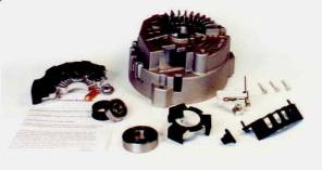
Image 041 Return
http://www.alternatorparts.com/7130_7140.htm
Standard "Iceberg Alternator"™ kit contains:
Exclusive "Iceberg" Patented Finned Housing for
Better Cooling
Heavy Duty Rectifier with 50 Amp Press Fit Diodes. (OEM use
only 35 amp diodes)
Copper Heat Transfer Grease for Better Rectifier Performance
and Life.
10mm Wide Rear Bearing. (original uses only a 8mm bearing)
Brush holder Assembly
Bearing Tolerance Ring
Drive End Bearing with Retainer
Positive
Three Stator Lead Extensions
Stator Lead Cover
In the Image 042 below, you can see the kit for the 140-amp
upgrade as it includes the additional rewound stator.
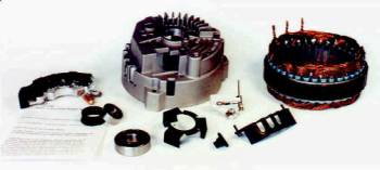
Image 042 Return
140 Amp "Iceberg Alternator"™ kit contains:
Exclusive "Iceberg" Patented Finned Housing for
Better Cooling
Heavy Duty Rectifier with 50 Amp Press Fit Diodes. (OEM use
35 amp diodes)
Copper Heat Transfer Grease for Better Rectifier Performance
and Life
10mm Wide Rear Bearing (original uses only an 8mm bearing)
Brush holder Assembly
Bearing Tolerance Ring
Drive End Bearing with Retainer
Positive
High output 140 Amp Stator (OEM CS-130 alternators have
85-105 amp stator)
Stator Lead Cover.
Return
Getting back to the CS-series alternators, the diode trios that are used in the
“SI-series” rectifier diodes have now been dropped, and the CS-series use
avalanche diodes instead. These are capable of handling 55 or so amps in the
better regulator/rectifier circuits in the aftermarket suppliers.
There are at least 14 aftermarket regulators for the
CS-series alternators that I personally know of, and I certainly do not know
them all. Delco calls their rectifiers All Silicon Voltage Regulators (ASVR),
alluding to the fact that these upgraded regulator designs are indeed computer
chip designs. They also refer the alternators as “Generators” now.
By the way, if you would like to take a peek at the various
regulators for the SI/CS-Series alternators you can click on the following
active link.
http://www.usi.com.tw/pdf/car/Delco_Regulator.pdf
These regulators are what are referred to in the electronics
industry as Application Specific Integrated Circuits (ASIC’s), and as such, the
original designs by Delco/Remy have been reversed engineered by aftermarket
vendors in order to make a higher profit margin by providing their own versions
of these regulators in remanufactured/rebuilt alternators. Some aftermarket
units are better than others are; none are likely to be as reliable as OEM…or
as expensive!
The terminals on the CS130 series alternator also have a
different design, as depicted in the schematic diagram below.
Earlier we discussed the 10-SI and 12-SI regulator circuits,
where transistors were used to provide a solid-state switch for the return path
of the field voltage by opening and closing the path to ground. These have been
in use for many years.
Note that while the overall concept is the same for the
CS-series generators, the “base drive” to switch the field magnetic strength on
and off is now controlled by a pulse width modulated train of varying duty
cycle pulses that controls the amount of current on the field windings of the
rotor thus giving finer control over the magnetic field generated by the rotor,
which in turn impacts the stator winding output. Thus the term ‘Generator” is
now being used by Delco, I suppose that this is the reason they cost so much
more now.
Image 043 Return
CS-130 Series Voltage Regulator/Rectifier
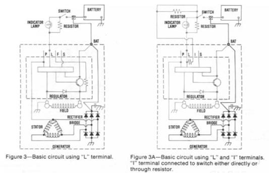
Image 044 Return
Image 045 Return
In the 045 Image, you can see how a voltage divider circuit
can be utilized in order to give the end user further control of the regulator
as one might wish to send the “S-Terminal” a lower voltage, thus causing the
regulator to slightly increase the alternators output. This might be used to
mitigate some additional loads on the alternator, especially if switched in on
a vehicle whose RPM range will not get much above idle and excessive amperage
loads are used such as rock crawling in the night with heavy off road lighting.
Examine the CS-series amperage vs. rpm charts to determine your crawl speed
engine rpm and resulting amperage output.
An example of who might benefit from this might be those of
you with a CS-series alternator and a crawl speed of 2000 rpm, you might only
be getting 45-65 amps from a stock set up alternator rated at 100 or 105 amps.
As a side note, please be aware that the above configuration may not work on
all CS-series regulators. Some regulators will respond fine just using the
S-Terminal as depicted above and no Lamp connection. Some CS-series regulators
may only require the I-Terminal to be connected to an Ignition Source, and
therefore will work fine without any other wiring connections. The circuit
would work by having a normally open switch installed on the dash, and by
closing the switch the resistor voltage divider of 430 Ohms and 2200 Ohms would
act to lower the voltage at the "S-Terminal".
As an example, if the voltage at the Vbat (or the
alternators output) is 13.5 Vdc. The regulator sense circuit (on a regulator
circuit set up to limit the charge voltage to the battery at 13.45Vdc) would
begin to shut down the charge being sent to the battery. So, 13.5 Vdc divided
by 2630 Ohms (the sum of both resistors in a series configuration) would give a
current of 0.0051330798479087 amps or about 5.13ma. When the switch is closed,
this 5.13ma flowing through the voltage divider circuit now develops a voltage
across the 2200-Ohm resistor of about 11.3Vdc. So now, even though the
alternator output is 13.5Vdc, it senses that it is only providing 11.3Vdc to
the battery and thus starts to charge the battery.
This is useful for those who wish to up the charging rate
that the alternator puts out without replacing the alternator or swapping out
the internal regulator circuit. Your light now become brighter and all loads on
the battery will be improved by supplying a higher voltage on which to operate.
I think that voltage regulator set points in our Jeeps work better at 14.8Vdc
than at the lower rate of 13.5Vdc simply because of the IR drop (that is the
drop in voltage thru all of the wiring and connections that the voltage and
current must navigate before arriving at the big splice inside the dash that
distributes the voltage to all of the inside of the cab loads). Return
Be careful to monitor the voltage across the battery
terminals does not rise above 15Vdc, if it does the battery might be charging
excessively and thus boil off electrolyte and overheat and short out. Pay
attention! After saying all of that lets be clear on one point, a set up like
the Image 045 will not change the amperage output at any specific rpm, it will
only allow the alternator to keep running when the battery reaches its
regulator set point that turns the alternator off after sensing that the
battery voltage has reached the regulators set point.
Image 046 Return
Section 4…”Some practical upgrades
for the do it yourself types (DIY)” Return
Here is a good CS-series Heavy Duty aftermarket voltage
regulator for use in rebuilding your alternators. It is a Transpo DR411XHD with
a set voltage of 14.8Vdc and a Load Response Control interval of 2.5 Seconds.
It is a PLIS regulator and therefore only needs the L-Terminal to be fed from a
lamp circuit, if you do not have a lamp circuit, then give it a 100-ohm
resistance of ½ watt in series with a switched 12Vdc feed.
http://www.transpo-usa.com/Images/pdf/5_Techup_ASVR.pdf
Here is a US Patent application image of how these
regulators are constructed. There is a computer circuit chip installed that
handles the 400 Hz Pulse Width Modulated signal that is sent to the Rotor Field
Winding. This gives a much tighter and smooth control over the Stator’s output.
The heart of the regulator is the item 106 in the lower image. This is reason
that you do not just disconnect the battery to see if the engine dies, it most
likely will either kill that computer chip, or seriously degrade the life
expectancy. Item 490d in the third image is the voltage regulator itself, an
integrated circuit L4896 from STMicroelectronics.
Image 047 Return
Image 048 Return
Image 049 Return
Here is additional information…the Voltage Regulator above
is the L9468 STMicroelectronics that uses a Pulse Width Modulated square wave
for control, the datasheet for this regulator may be viewed at this URL:
http://www.st.com/stonline/products/literature/ds/11314.pdf
Image 050
 Image 051 Return
The
CS-series of alternators use a 4 terminals of the above voltage regulator, with
the
following connector pins:
P-Terminal: Terminal P stands for Phase and
is normally connected to the Stator and on a healthy alternator this terminal
will send out a signal to tell a vehicles computer how hard the alternator is
charging. The Pulse/Phase terminal provides a 12V square wave that
represents alternator rpm speed and is used by some
electronic control modules or vehicle computers. This terminal connects to the
stator and develops a square wave that is proportional to the revolution of the
alternator stator. Some vehicle computers monitor this signal and adjust engine
parameters accordingly.
L-Terminal: This terminal is connected to the
“Low” side of the warning lamp, with the lamp's “High” side being fed by a
switched ignition circuit. Some regulators require a 35-ohm resistance inline
with this circuit if no lamp is used otherwise alternator damage may ensue.
Some applications have a resistor connected in parallel to the lamp in case the
lamp bulb opens up and burns out. The resistor will be there to provide a path
for current and voltage. Some vehicles supply a 5Vdc reference to this terminal
from their ECU or Computer; other vehicles do not, so be aware of the various
models of regulators. Other regulators may be tested by application of a 50-Ohm
pull-up resistor to connect the L-Terminal to the 12Vdc source, I believe that
any resistance between 35 Ohms (5-Watt resistor) and 500 Ohms (1/2 Watt
resistor) can be used safely, but a better choice would be a 100-ohm resistance
to limit the current to something around 120ma. This current is normally
limited by being supplied though the lamp circuit, from the idiot light on the
dash. Terminal L stands for Light or Lamp and is connected to the idiot light
you can test this by purchasing a pigtail connector and wiring a No. 53
incandescent bulb in series with the L-Terminal. The pigtail will also use the
S-Terminal to determine if it is ½ of the charging voltage. When you connect
the L-Terminal to the positive battery post the lamp should light. You may now
start the vehicle, if the lamp stays on, the alternator is suspect, and you can
measure the voltage on the S-Terminal. The lamp should go out when you start
the vehicle. The lamp bulb is rated at 120ma and is used to limit the current
to the L-Terminal. Connect that L-Terminal directly to the battery and you have
just ruined your regulator! Most of the CS-Series alternators will operate with
only the L-Terminal connected. The L-Terminal is grounded by the alternators
regulator circuit when the alternator is not charging (as in engine off and not
running), when the engine is started and the alternator begins to charge, the
regulator disconnects the ground for the L-Terminal and therefore the lamp
should go out, because there is now an open circuit to ground and no current
may flow. L
I/F-terminal: This terminal performs several
duties depending on the specific regulator. Some regulators have a resistor
that is internally connected between the Field and Lamp terminal. Other
regulators use the F/I terminal to provide field duty cycle information to the
vehicles Electronic Control Module (ECM) or computer. These regulators are not
interchangeable, but for our Jeeps, it hardly matters. For ECM related
vehicles, it can be of paramount importance. If the alternator that is selected
comes from a vehicle that only uses the L-Terminal then you would simply supply
a wire from the low side of the alternators "Idiot Light" in order for
the alternator to operate correctly. These
are not used, for the F-Terminal; some vehicles have something called a Body
Control Module (BCM). For those vehicles, that DO NOT have a BCM this connects
the voltage regulator to a voltage source. If the vehicle does have a BCM this
terminal tells the BCM how hard the alternator is working, in other words, it
is really a field coil connection, and therefore it should have a resistance to
ground since it connects to the field winding coil. Where the vehicle uses the
I-Terminal, it is only used on vehicles without a BCM and receives 12Vdc
through some resistance to operate the regulator. Some vehicles use this
terminal to connect to the Stator field and on a healthy alternator this
terminal will read about ½ of the output of the alternator. Therefore, if the
alternator is outputting 14.8Vdc, you should read 7.4Vdc +/- 0.50 volts. It is
generally too confusing to sort out which I/F regulator you might have,
especially if you go to a junkyard and pull it off of some shelf that houses 75
other CS-Series. You really need to be positive about the vehicle it came from.
For instance, Honda’s use a CS-Series alternator, but the connector in the
alternator is square! Just stick with the recommended alternators down further
in the article and you will be fine. Some I-Terminals connect to the vehicles
Ignition Circuit. Not so clear, eh? No worries, mates…just do not use these
terminals.
S-Terminal: The Sense terminal may be
connected to the battery or at a point in the harness to monitor the actual
voltage you are sending to the load. This heavier gauge terminal spade lug is
connected to the battery. This terminal is the “Sense” circuit and provides the
regulator a voltage reference. The S-terminal on the CS-130 regulator is larger
than the other three terminals.
It is next to impossible to know if a PL(I)S or a PL(F)S
regulator by simply looking at the alternator when installed into a vehicle. If
it is installed in a vehicle, then the vehicle; such as a Cadillac, might have
an electric defrost circuit on the rear windshield and that will tell you that
the extra terminal on the rear of the alternator is used for the Stator AC
Waveforms used to heat up the window.
You might have to take the case apart and check the part
numbers on the voltage regulator. Most, if not all, manufactures have started
to stamp the nomenclature of the terminals on the connector so that they may be
read, and it is becoming much easier to ferret out information.
We have examined one PWM Voltage Regulator, there are,
however many to choose from and the manufactures will use whatever suits them
at the time. There are apparently methods to bench test and determine the
regulator type, but this is best left to folks who have access to the various
cross reference documentation and is beyond the scope of this particular
article. The documentation may be purchased at outlets that support the
alternator servicing community. If you know the make and manufacture of vehicle
that the alternator is designed for, then you can probably track it down,
however who can say what has happened to an alternator that has been rebuilt.
Anything could have been replaced.
Some of the regulator circuits stamp either the
“I-designator” or the “F-designator” on the plastic housing; others however do
not do this. Just be aware of the variations. Some regulators have PL(I/F)S
terminal markings, so it can get confusing at times. With all of the different
regulator circuits out there, some in depth knowledge is required so that damage
to the regulator circuits do not occur, and there are a plethora of designs out
there, both OEM and especially after market.
Another caution is in order here; the ASVR and earlier
regulators in the CS-Series alternators can easily be damaged by improper servicing
techniques. Please observe the following precautions when removing or
installing these alternators.
Removing
CS-Series Alternators… ALWAYS DISCONNECT the Negative Battery Cable before
doing anything, and ensure that the engine is not running when you do this.
DISCONNECT the PLI/FS voltage regulator connector before
disconnecting your BAT terminal and DISCONNECT the BAT terminal last.
The alternator is now ready to be removed.
Installing CS-Series Alternators… ALWAYS
DISCONNECT the Negative Battery Cable before doing anything! Install and secure
the alternator with the mounting hardware
Attach the BAT terminal before connecting the PLI/FS voltage
regulator connector, attach the PLI/FS voltage regulator connector, insure
belts are tensioned properly and there is no interference with the alternators
terminals. Connect the Negative
The CS-130D Alternators have the following connections…NOTE:
ALL OF THE TERMINALS on the CS-130D regulators is the same size.
P-Terminal: Provides a 12Vdc square wave as
in the CS-130 application that is proportional to the alternator rpm’s.
F/I-Terminal: It gets a bit tricky here, as
some applications do not incorporate a lamp circuit. In vehicle applications of
the “no lamp” kind, this terminal is connected through a switched ignition
circuit and an internal resistor is used to limit current and voltage. Other
regulators use this terminal as an output and refer to this pin as a Field
Terminal, as such, it provides an output that is proportional to the field duty
cycle of the alternator to a vehicles ECM. The ECM now has an input to sense
alternator loading and engine loading, and can increase/decrease engine RPM
speed accordingly. Here is an important consideration, since the regulators on
CS-130D type alternators have these two different types of regulators (F-Type
or I-Type) they cannot be interchanged. I-Type regulators use the F/I-Terminal
as an input and this can simply be an ignition source 12Vdc voltage that the
alternator uses; F-Type regulators use the F/I-Terminal as an output (this is a
signal that is provided to the vehicle computer and the computer uses it to
monitor the field intensity of the alternator as an input). If you supply a
12Vdc signal to this input, you may very well ruin the alternator's regulator.
L-Terminal: This is the lamp terminal and
operates in the same manner as the CS-130 lamp circuit above. It is of interest
to note that some applications use the ECM to send the L-Terminal a signal
(5Vdc reference), and the F-Terminal responds with a signal returned to the
ECM, in this application the ECM and the Regulator form a “closed loop” to
control engine loading and alternator output.
S-Terminal: This is the “Sense” terminal and
is connected to the battery. It senses the voltage level of the battery and
feeds the regulator circuit this reference so that the regulator can adjust the
Pulse Width Modulated signal to control the alternator's Stator output. The
S-terminal on the CS-130D regulator is the same size as the other three
terminals, unlike that of the CS-130 (where it is the largest terminal on the
regulator).
Since these CS-series, regulators are now essentially an
electronic computer chip, ALWAYS disconnect the battery before servicing, and
do not EVER remove the battery cable when the engine is running. If you simply
must do this, you may have just destroyed the regulator's computer chip. Not
all of the regulator in the CS-series of alternators will be damaged, I do not
know which ones will be damaged, do you? You must really begin to think of
these alternators as electronic devices with specific guidelines on how they
are handled. Return
CS-Series alternators use diodes within the rectifier plate
known as avalanche diodes. Original equipment designs use avalanche diodes with
a forward voltage of 0.9V @ 100 Amps.
There is an up and a down side to using these devices. On
the up side, they do a much better job of preventing damage and surges, current
spikes, and such from reaching sensitive electronic equipment inside the cab
and under the hood. Your upgraded stereo equipment will fare much better than
using high amp SI style alternators.
On the down side, due to the nature of their operation,
their lifespan is not as long as the earlier diode trios used in 10/12-SI
alternators. Still, many years of service can be expected, just not decades as
in earlier alternators, I believe that the service life of the CS-series
alternators is somewhere around a 100,000 miles depending upon specific model
number (CS-121, CS-130, CS-130D and CS-144).
We do not need to go into Epitaxial Planar Diode structure,
just suffice it to say that the OEM regulators and diodes are tested and
function the best. Try to stick with alternators that were rebuilt with OEM
parts, you will generally get a better quality rebuild. I have had good results
in rebuilding my CS-130 with Transpo components, and they meet and in some
cases (severe duty applications) exceed OEM specifications.
As an aside, on the subject of diodes that are used in the
CS-130D series of alternators, consider the following. A CS-130D with an output
of 105 amps uses a three-phase stator with a 6-diode bridge rectifier. Each
forward biased diode in the array will have 35 amps running through it. AC is
rectified on positive voltage waveform fluctuations. Three phases equate to
three diodes in the positive and three diodes on the negative voltage swing
(these last three block the negative going voltage so only the positive voltage
swings are sent on). Each of the three diodes will have about 1Vdc drop across
it, which equates to 35 watts per diode (35 amps with 1Vdc forward bias voltage
drop) or 35Volt/amps (35 watts)…times three, or 105 watts of heat generated by
only the diodes themselves. Dual fans are necessary to cool these units.
So stick with the OEM replacement parts and spend the extra
$15-$20 dollars for OEM regulators and rectifiers just to be on the safe side,
when you have these generators rebuilt. By OEM replacement parts, I am
referring to parts that meet or exceed OEM specifications. Many advertisements
claim to meet this minimum threshold, let the buyer beware.
Most of the CS regulators use Application Specific
Integrated Circuits (ASIC). More to the point, Application Specific Voltage
Regulator (ASVR) computer designed chips, which may be encased in a plastic
housing or a heat dissipating enclosure of metallic structure.
As a side note, Delco refers to their ASVR regulators as All
Silicon Voltage Regulators. I would opt for the metal encased regulators, and
yes, it WILL cost more.
A word about aftermarket products and alternators purchased
at some of the lower tier automotive aftermarket outlets.
In the VAST majority of cases, the only things that go wrong
on alternators are the brushes wearing out (resulting in a weak magnetic field,
this can be easily checked by placing a screwdriver against the alternator
case) or the internal regulator/rectifier or diodes going bad. Unlike the 10-SI
or 12-SI units, repair of the CS-series alternators by the nonprofessional is
not nearly as simple as it used to be.
The diodes usually short out or begin to “leak”, this is why
many Jeep owners first notice a battery drain, and in the morning, the vehicle
does not start. Avalanche diodes have their p/n junctions harmed by heat, and
when new, they block battery current frond m flowing to ground while allowing
field current to continue to flow. So they may still operate the alternator
will still provide an output charge, these leaking diodes are subjected to
excessive heat due to their leaky status.
When the regulator goes, generally overcharging or
undercharging are the symptoms, and if you have the “L”-terminal connected to
an interior lamp, the lamp should begin to glow, giving you a fault indication.
So, if the lamps lights then look for an under voltage or over voltage symptom,
or perhaps a wiring fault.
So…brushes are cheap, $10 dollars will usually suffice, and
diodes are not expensive either. Rectifier/regulators (good OEM versions) will
cost in the neighborhood of $40-$50 dollars.
The regulators may ship with new brush assemblies, and the
regulator circuit is mounted on a heat sink and can be replaced, most
brush/regulator assemblies cost under $60 dollars. These new regulators are
built on surface mount technologies on thick film hybrid electronics packaging
utilizing third party Computer Aided Design/Computer Aided Engineering designs,
chip and wire welding flip chips assembled on modern production lines, to
shorten the period from customer order, material control, manufacturing
process, quality control and customer delivery. (Customers in this particular
sense are the aftermarket suppliers to the rebuilding trade industry)
Return
Whew, it is a wonder they work at all, eh?
I will point out that de-soldering the lead connections of
the stator field coil wires can be “problematic” (PITA) if not done correctly.
Otherwise, the only items generally needing to be replaced
when overhauling these units are the regulator and the brushes. About $75-$90
dollars, tops, and your time and skill to remove, disassemble, repair,
re-assemble and reinstall the unit. This assumes using high quality replacement
components. Parts houses will generally use much cheaper components, in many
cases they might not spend more than $30 in parts.
Bosch seems to do a good job on rebuilding the CS-130
alternators, and these units are priced reasonably.
Well, there is my rant on the subject…
Now, to get a bit practical, here is what you can do for
your Full Size Jeeps.
For you
guys and gals who want a CS-Series alternator for your Jeeps but do not want
the hassle of searching parts yards, AutoZone sells a CS-130 105-amp alternator
that will fit our Jeeps.
It is a Duralast Gold alternator made by Johnson Controls
(they make Interstate and Sears Die Hard batteries). These alternators are
completely rebuilt using ALL NEW components, and they provide lifetime
warranties. So putting down $140 dollars buys an alternator, the interface
pigtail made by a quality company and will last you a lifetime of service, and
AutoZone locations are everywhere.
The CS-130 model number you want is a DLG1352-5-11, this
unit will set you back $125 dollars with a $10 dollar core charge. This
translates to a Duralast Gold (DLG) 1352 (CS-130 105-amp alternator with
mounting ears at 12:00 O-clock and 6:00 O-clock) with a five groove serpentine
belt and an 11 O-clock clocking position (where the connector plug on the rear
of the alternator is at the 11 O-clock position as viewed from the front of the
alternator). Once you buy this alternator and the associated 4-pin regulator
conversion pigtail that will be required for it (about $17 dollars) that is the
last alternator you will ever need to purchase for the lifetime of the vehicle.
If the alternator fails, you just go down to the local
AutoZone and get it replaced free. They do charge a core charge ($10 dollars),
so be sure to save that old 5 or 6 groove serpentine pulley to place back on
the unit if for when it needs replacement, you will need an impact wrench to
get the nut off of the pulley.
Return
One CS-144 model that you might want is an O'Reilly Auto Parts (other parts
houses are listed below) alternator for a 1986 Buick La Sabre front wheel drive
with a 3.8 Liter V-6 engine (Engine Code B) which has the correct CS-144
alternator for our Jeep applications. It is rated at 120 amps, and has a single
“L-Terminal” and can be fed from an ignition switched 12Vdc source. Delco-Remy
rebuilds these using all new parts and they utilize some great OEM components,
with the additional benefit of a Lifetime warranty. That part number will be an
Ultima Part Number 01-0369 for $115 dollars with a core exchange ($25 dollars),
it gets a lifetime warranty.
Here we find a Billet Aluminum Serpentine Pulley system with
support for Air Conditioning.
http://www.bulltear.com/catalog/product_info.php?products_id=243
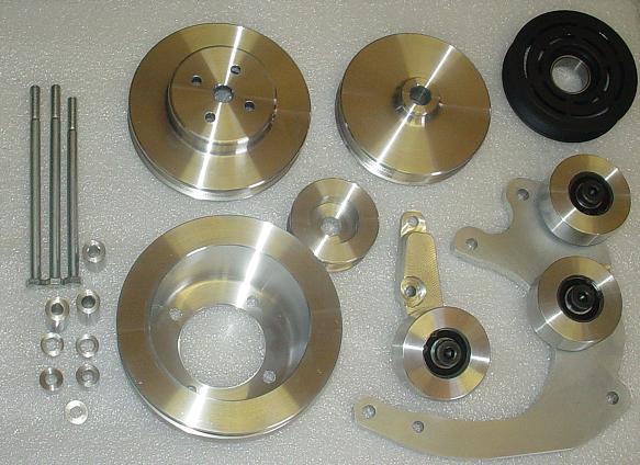 Image 052 Return
Again, for those of you who want to keep your wiring harness
intact, there are also adapter harness pigtails that Delco sells that convert
your existing Jeeps SI alternator harness plug to plug into the CS-144
alternator. An additional backup feature of this type of set up is no modification
of the existing wiring harness, and you are now able to use either SI or CS
alternators at will.
Return
These SI-to-CS harness adapter pigtails have a Molex connector to interface
with the existing wiring harness SI style Molex connector, and the Delco
Weather Pack connector to fit the CS-130 and CS-144. The following are the
SI-CS conversion adapters with and without the internal resistors for the
“L-Circuit”.
Delco P/N 8077 (you MUST have an “Idiot light” as this P/N
does not include a resistor) Delco P/N 8078 does include a 350-Ohm resistor
Haywire P/N 2110
Painless Wiring P/N 30707
Image 053 Return
Delco makes a SI-CS conversion adapter that includes the
resistor for the “L-Circuit”, and this resistor duplicates the electrical
characteristics of a Lamp Circuit. I have not checked this part out yet, to
measure the resistor that they include, but suspect that it is probably a
350-Ohm resistor in series with the No. 1 terminal connection of the SI-plug
(in your existing wiring harness) that is re-routed to the “L-Terminal” of the
CS-Series plug.
The part numbers are Delco P/N 8078 General Motors
P/N12102921 Pico P/N 5331, these part numbers will change as this article was
originally written in January of 2004, so your vendor might have to cross
reference the part number to the correct item.
Quick Start
Item Number D1W1201 Adapts 10 thru 27 SI Vehicle to
CS-130/144 alternator. For Vehicles that DO HAVE a "no charge"
warning light No Resistor in Harness
Item Number: D1-W1204 Adapts 10 thru 27 SI Vehicle to
CS-130/144 alternator Used on Vehicles NOT HAVING "no charge" warning
light, Ignition resistor in wire harness
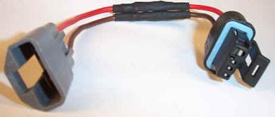
Image 054 Return
At the bottom of the page in the following link, you will
find both of the above adapter’s harness connectors.
http://www.alternatorparts.com/Extreme%20Duty%20Dual%20Rectifier%20CS-144%20type.htm
Some different model Jeeps may have serpentine belts, so
perhaps it will fit perfectly, however I am not at all sure of this, I have
just heard rumors that some Jeeps have serpentine belts. Need to do a bit more research
on this issue and edit this document with the result, so for now this is merely
speculation, you can best determine your specific requirement, right? If you
have a Jeep with a serpentine pulley please e-mail me with details so that I
can include this into the document and update. I do know that there is a fellow
on the IFSJA site that provides serpentine kits and with this edit has given
that information. In any case, go ahead and email with comments or concerns as
they arise. joe_guilbeau@yahoo.com
Section 5…”How to Guide” upgrades
for you penny pinchers out there…” Return
For you DIY-types, to find an alternator that will fit your
Jeep, you can take your alternator to a pick and pull junkyard, and look for a
'85 to '90 Chevy or GMC product, like a truck or (in my case) a rear-ended
Chevy Corsica, or Lumina. I got a brand new CS-130 105-amp output unit that had
been recently installed.
The Delco sticker was still bright white, and shiny, and the
unit looked like it was placed in the vehicle the morning of the accident, our
local pick-n-pull has at minimum 3000 vehicles and cost $1 dollar to enter and
browse, so on slow days I go down and locate items of interest and note on a
map drawn of the yard where the item is located and the model and year and
engine of the donor vehicle. Then I try to research the item of interest to
determine the value to me. Look for a 12 O-clock and 6-Oclock mounting with a
10:30-ish or 11:00 O-clock position for the model you choose. Refer to the
10-SI picture (rear side) to visualize what will work. The Buick LeSabre's of
1986 with 3.8 Liter V-6’s and engine code “B’s” will do nicely with a CS-144
for you.
CS-130D’s can be found on Trucks, Caddy’s and the CS-144’s
are available on heavy-duty applications. Some for ambulance versions, as the
load that they are required to support is”critical” and the alternators output
at idle is very stable and higher than the “run of the mill” units generally
available.
Return
So, getting back to our junkyard alternators, pull the alternator, on the way
home, stop at any Auto Parts store, and have them check it out on a test stand.
After the unit is found to be good, buy an appropriate connector to plug into
the back of the alternator, do not forget this little detail, or back to the
store you go!
If it is bad, I hope the bone-yard will allow you to return
it. Get their “lifetime warranty” guarantee, it will save a bunch of money in
the long run, and waste quite a bit of your time in the mean while, but this is
a DIY type project, otherwise why bother reading all this information?
The pulley will have to be changed, as most of the Chevy/GMC products use a
serpentine belt, most FSJ’s use a V-belt.
Anyone with an impact wrench (tire change shop or garage that fixes flats) can
do this for you, just stop by and offer a dollar for the greasest/natiest
clothed guy there to remove it for you, I have never been turned down,
especially if you time it just before lunch… timing is everything… eh?
Take the front cover off, and using your old alternator as a pattern to refer
to, "re-clock" the front housing so that the alternators rear plug in
harness will be in the same orientation as your old alternator, and the
mounting holes line up the same as the old alternator. Additionally, ensure
that the Plug Housing and the Generator output threaded post do not place the
associated wiring in close proximity to your exhaust manifold.
So, what is a clocking that I am referring to? Well, on
these alternators this is an analogy to a clock face and the position of the
regulator’s connector. Holding that alternator up and viewing from the back of
the alternator with the mounting hole at the “12 O-clock” position, note where
the regulator connections are oriented on the “time piece face”. The connector
plug should be at the 10:30-11:00 O-clock position. The following depicts a
12:00 O-clock orientation (see the regulator terminals at the top?). You will
want a 10:30/11:00 O-clock orientation.
Image 055 Return
By re-clock I mean that the two piece housing can be pulled
apart, and the pulley side of the housing can be turned either clockwise or
counterclockwise in order to ensure that the mounting hardware and the back
plug are oriented the same way as the old alternator, which allows you to plug
in the harnesses and connect the output of the alternator so that no shorts, or
excessive heating occurs as might be the case if the wire harnesses were
allowed to connect to the exhaust manifolds.
Here is (I believe) a major culprit of Jeep fires and burned
wires, simply an error in mounting the alternator, and not re-clocking properly
on an aftermarket alternator purchase. Go figure….
Otherwise the plug in harness may go up against the exhaust manifold...not
good, and the tensioning bolt hole will not be in the right spot, also not
good.
Ok, go back to another tire place (or the same one) and get
the pulley installed on the CS130-series or CS-144 alternator that is your cool
new toy. (A touch of Lok-Tite on the threads will insure secure mounting)
You are ready to install, total out of expense so far should be about $30
dollars. The BATT goes directly to the solenoid post that connects directly to
the positive battery post.
The "L"-Terminal can be used to supply the voltage "sense"
to turn on the alternator. On the older FSJ’s there was a wire resistor feed to
Terminal No. 1 on the 10/12-SI units, this could serve. A better choice would
be to mount a light in the cab, and connect its high side to a switched 12Vdc
source from the Ignition Switch and the low side to Terminal No. 1… waits a
minute…there is already such a wire in the harness, the resistor wire. So
replace it with a better insulated resistor wire, and that takes care of the
L-Terminal pigtail on the new connector.
The “S”-Terminal can be fed from the
The “I/F”-Terminal is a bit tricky. If the vehicle that the
unit came out of did not have an idiot lamp, then this terminal was probably
fed from the Ignition Switch thru resistor wire. More importantly, other
regulators used the “F” designated ion of this terminal, and if this is the
case, this terminal will be an output to the ECM of the vehicle feeding a 12Vdc
square wave to the module so that it can monitor the loading on the Alternator
and adjust variables as it sees fit.
If you were paying attention earlier, I already mentioned
this, but it bears repeating…
“…The ECM now has an input to sense alternator loading and
engine loading, and can increase/decrease engine speed accordingly. Here is an
important consideration, since the regulators on CS-130D type alternators have
these two different types of regulators (F-Type or I-Type) they cannot be
interchanged. I-Type regulators use the F/I-Terminal as an input; F-Type
regulators use the F/I-Terminal as an output and therefore cannot be
interchanged…”
So, if it is indeed an F-terminal regulator, do not connect
it unless you know what you are doing. The CS130D and CS144 alternators are an
improvement on the CS130's, but may need aftermarket brackets in order to fit.
Any alternator/rebuild shop can get it done so ask them to install an OEM DELCO
ASVR, if they are not comfortable with the Transpo aftermarket parts.
Now please understand that I skipped over a plethora of technical issues on
this post, but it will give you a general idea of the charging systems on these
old FSJ's, and I know my wiring instructions are pretty sketchy, so many details…so
little time. Jeep FSJ’s were made from the 70’s to the 90’s and there are
variations in the wiring. Additionally, there are other items to consider, such
as the conversion plugs for SI-to-CS and which CS-Series alternators is the
best for your particular application.
One note of interest here, is that if a CS-144 is chosen,
and then Mobi-Arc sells a Mobile Welding unit that has received good reviews
that can use the CS-144 (you must change out the regulator for NON AVALANCH
diodes) and for about $600 additional dollars you can weld up to ¼-inch stuff.
Therefore, this might be worth considering.
Just do not go out there and burn up your vehicle because
you read this, and do not fully understand what it is that you are doing. I am
writing this so that those of you may better understand these systems, and may
benefit from some of the info presented. If you do put in one of these more
powerful alternators then the rest of the system must be up to par!
For instance, that CS144 Iceberg upgrade for the $18 dollar
“You-Pull-It” parts yard is now installed and you are beaming with pride. Now
you have the amps to get that ghetto-blastin-rockin-shockin-stereo installed.
Unfortunately, you neglected to upgrade the wiring in your
ammeter circuit, and the alternator output has just contacted the exhaust
manifold and has now burned your FSJ to the ground…DOH!
The diagram below shows how one can upgrade the wiring,
alternator and ammeter gauge to keep your Jeep in top electrical shape.
Image 056 Return
The above image was made with a trial copy of SmartDraw,
CAD/CAM evidently is above my pay grade, and I thank SmartDraw for the
opportunity to embarrass myself.
http://www.smartdraw.com/downloads/
We start by replacing the existing battery cables with #2
Welding insulated cable. This gives us a solid ground connection and with the
additional #2 Welding cable going from the other post on the Starter Solenoid,
we have a great current carrying circuit available so that the Starter spins
faster due to increased voltage and current availability. This in turn reduces
the load on the alternator and the battery as well, since less amps are drawn
to get the Jeep started.
With the wiring upgrade in the Alternator to Ammeter with
the SXL Red 6-AWG wire, there is less heating of the wire and less cable loss.
The Ammeter Solenoid cable has also been upgraded with the addition of the SXL
Yellow 6-AWG wire, along with upgraded protection with the addition of an ANL
Fuse rated at 150-amps, replacing the fusible link wire that the Jeep
originally shipped with. Now, if there is a problem, you do not have a burned
up harness or fusible link, just replace the fuse; which protects far better
than the slow burning fusible link. The 150-amp fuse rating was chosen for a
104-amp CS-130.
We may opt for an Ancor thru bulkhead connector Blue Sea P/N
1001 that is waterproof, and included strain relief. It mounts to the bulkhead
with ½” NPT threaded posts and the unit includes a synthetic rubber gasket,
thus bypassing the OEM bulkhead connector.
![]()
![]()
)
Image 057 Return
http://bluesea.com/productline/overview/1
The fuse holder is a Blue Sea P/N 5005 Fuse block with 5/16”
(M8) Terminals, and if you want additional protection use a 100-amp ANL fuse
Blue Sea P/N 5125. The fuse holder provides ¼” mounting screws to bulkhead. It
accepts up to 300 amp ANL fuses.
Image 58 Return
http://bluesea.com/category/5/21/productline/129
For termination of the 6-awg cabling, we will use Ancor P/N
252233/34/35/36 (depending upon how large the stud you are connecting to). Tin
plated copper heavy duty lugs that the cable is crimped and soldered to, with
adhesive heat shrink. Go ahead and purchase 8 of these terminals, with one to
use either as a spare or as a test model to insure the job is done correctly,
some of the options are shown below.
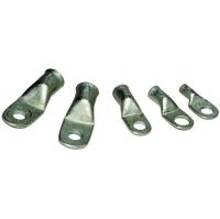
Image 059 Return
http://www.firstchoicemarine.com/p-19787-ancor-cable-lug-8-awg-10-2-pk-252233.aspx
The Westach Ammeter P/N 2C6-3 image is displayed below, for
a 100-0-100 Amp gauge. On their website there is also a P/N 2C6-14 which is a
150-0-150 Amp gauge.

Image 060 Return
http://www.westach.com/products/SINGLE/2%20INCH/AMMETERS/index.php
The Ammeter uses a Shunt Resistance to develop a voltage (in
millivolts), which is then sent to the above display meter, which in turn
drives the display needle. For those of you who wish to bypass the running of
6-AWG cable thru the bulkhead firewall, the shunt can be remote mounted in the
engine bay, and smaller gauge wiring can be considered for the millivolt drive
signal to the Westach ammeter gauge itself.
Do not forget to use the adapter harness below to interface
the harness with your new Delco CS-130 alternator.
Item Number D1W1201 Adapts 10 thru 27 SI Vehicle to
CS-130/144 alternator. For Vehicles that DO HAVE a "no charge"
warning light No Resistor in Harness
http://store.alternatorparts.com/partnod1w1201.aspx
Item Number: D1-W1204 Adapts 10 thru 27 SI Vehicle to
CS-130/144 alternator Used on Vehicles NOT HAVING "no charge" warning
light, Ignition resistor in wire harness
http://store.alternatorparts.com/partnod1w1204.aspx
Both of the above adapters may be purchased at Quick Start.
Image 061 Return
One other note, with all of the variations in CS-130, CS-144
and CS-130D alternators and their regulator circuits, it pays to know what
regulator circuit has been included in that re-built alternator that you pulled
from the junkyard. Therefore, when you stop off at that Auto Parts Store, have
the part guys/gals check it out for you. They will generally know, or the
management there will generally know who re-manufactures the alternators that
they sell.
Things
can get complicated with these new regulator circuits (computer chips) and that
is part of the reason that I have taken the time and effort to add to our
knowledge base.
Life is complicated enough, without having Jeeps that will
not start, or Jeeps that burn.
Return
I love FSJ’s.
The following part numbers and prices were accurate as to
11/30/2010.
Vendor Vendor
Part Number AMP Rate Pricing of CS-130
Napa Part Number 13-4521D 100 amp $124 Lifetime warranty
AutoZone Part
Number DLG1352-5-11 120 amp $125
Lifetime warranty
Advanced Auto Part Number P814513 124
amp $135 Lifetime warranty
O'rielly Auto Part
Number 01-0369 120
amp $115 Lifetime warranty
Return
Section 5…Reference materials to assist in your upgrades.
References:
Nice automotive electrical/electronics site
Some interesting reading, load the following page and go to
the Downloadable Reference Materials link, then click on the Reference
Materials… worth the effort!
Zener diode voltage sensing circuits and some applications http://pubpages.unh.edu/~aperkins/pdf/Misc-devices/unijunction.pdf
American Wire Gauge tables, amperage, and sizes http://www.rbeelectronics.com/wtable.htm
AC Delco Alternator Page
http://www.acdelcotechconnect.com/html/tas_alt_main.jsp
National Quickstart Alternator CS-130 manual http://www.alternatorparts.com/cs130_sbpage1.htm
Aircraft site talks about RF interference with alternators http://www.avweb.com/news/maint/182896-1.html
Transpo Electronics Inc.
http://search.waiglobal.com/prodsubcat.aspx?prodcat=AlternatorParts
MAD Electrical
http://www.madelectrical.com/electrical-tech.shtml
Basic Vehicle Electrical (with a slant to Car Audio)
United States Navy Electricity and Electronics Training
Series (24 Modules) http://jricher.com/NEETS/
Transpo Voltage Regulator Tester Model VRC 1000 http://www.waiglobal.com/techups/transpo/Transpo_Testing_Manual.pdf