FSJ Radiators and Cooling
By by Joe Guilbeau (09/19/04)
This article is a three part series addressing AMC Full Size Jeeps radiator cooling basics and system design, some key diagnostic troubleshooting tips and two different design philosophies that illustrate how the available components in the aftermarket can be utilized to achieve your cooling goals.
Radiators and cooling should be at the forefront of your maintenance and upgrade schedules for your Full Size Jeep. We will document several of the myriad design and equipment choices for solving overheating issues and will primarily address the eight-cylinder engines, although the overall concepts hold true for the six-cylinder mills as well.
Part 1 of this article addresses the basic system configuration of an OEM 5.9 Liter AMC-360 as it comes from the factory. After a brief synopsis of the cooling system components, we will touch on diagnostic and troubleshooting of cooling problems.
Part 2 of this article details a system that I am currently running on my 1983 Cherokee Laredo and has proven itself from here in Texas to Arizona and back in 115° F heat, crawling up Mount Lemon outside of Tucson or in the Big Bend National Park.
Part 3 of this article details another system design using an Aluminum radiator and an electric fan that is a turnkey solution to your cooling requirements.
It is a sad, but true fact that the cooling systems in our Jeeps are probably the most neglected and least maintained system in our Jeeps, yet it is relatively simple to comprehend and probably the easiest to maintain...with some basic knowledge.
Part One: Basic System Configuration and Diagnostic Troubleshooting
Our Jeep cooling systems are designed to allow the engine to reach a normal operating temperature as soon as possible and then maintain that operating temperature over the course of driving in a wide range of ambient temperature ranges and finally, to prevent any overheating that might occur. Coolants in the closed loop system are designed to absorb engine heat and transfer it to the radiator so that through convection and thermodynamics heat transfer may occur.
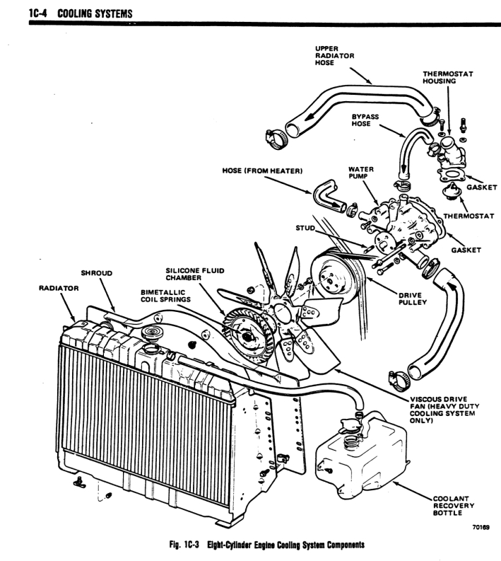
The below illustration depicts the components of an OEM 5.9 Liter AMC-360 Jeep engine of the mid-80's.
The centrifugal water pump impeller blades, at the center of the timing case cover, into both left and right banks of the cylinder block areas circulates the coolant. The water jackets there route the coolant around all of the cylinders, up through some holes in the cylinder block area, and then to the cylinder heads through additional water jackets. There additional heat is transferred to the coolant by the exhaust valves. It continues to flow through the front of the cylinder heads into the intake manifold and to the thermostat.
The right cylinder head (passenger side) routes the coolant to the intake manifold water jacket to an outlet at the upper rear of the intake manifold, which is the inlet hose for coolant flow through the heater core. If the controls inside the cab are adjusted to open the heater valve, coolant is routed through the heater core. If the heater valve is closed, the coolant is routed through the intake manifold to a bypass hose back to a fitting on the water pump, which in turn, is pressurized via the impeller blades.
This continues until the thermostat reaches its set point and begins to open up, allowing coolant that has been trapped in the closed loop system to reach the radiator intake inlet at the top of the radiator tank, which is fed by a radiator hose connected to the thermostat housing. Before the thermostat reaches its set point and opens, coolant flows through a bypass hose that routes it from the thermostat housing to the top of the water pump. This allows the blocks heated coolant to circulate so as not to create hot spots in the engine.
Once the thermostat begins to open, the impeller blades of the water pump force coolant to flow through the radiators cooling tubes and out of the lower radiator outflow outlet to the intake of the water pump via the lower radiator hose. This hose should be stiff or reinforced so that it does not collapse. If wire enforced, inspect yearly to insure that the wire inside the radiator hose is rust free.
Coolant passing through the radiator is cooled by air passing over the tubes and fins of the copper/aluminum radiator and is assisted by the radiator fan and the vehicles forward motion. Some radiators are equipped with automatic transmissions tubes, and the coolant inside these radiators will pick up additional heat loads from this source. After the coolant reaches the water pump, the impeller blades continue to pressurize the water to force it through another circulation cycle, and as the thermostat continues to open, the coolant reaches a maximum flow rate which is determined by the passage rate of the coolant through the block passages, the heater core (if open) the thermostat and the amount of coolant that the impeller blades of the water pump can move through all of these restricted water passages, least of which are the radiator tubes.
In addition, the heated coolant will begin to expand and further pressurize the closed loop system. Most systems allow this pressure to be bled off via a radiator pressure relief cap rated in the neighborhood of 12-15 lbs. of pressure. There is a coolant recovery tank that collects this overflow condition. For every lb. of pressure exerted on water, the boiling temperature is raised by 3°F. Normal sea level temperature for water to begin to boil is 212°F, so with a 15 lb. radiator cap installed, the water temperature inside the engine block can reach a temperature of 257° F, before it begins Nucleate Boiling.
So, a strong word of caution is needed here, as this is a very dangerous level of pressurized water that is far past the boiling point, and may very well become pressurized steam in less maintained systems. Needless to say that this is very dangerous to come in contact with. So be very, very careful, otherwise skin grafts and many months of recovery will almost bring you back to where you were before any mishap scalded you.
Here is a quick experiment so that the reader can visualize the principals of Nucleate Heat Transfer, where the water passages near the exhaust manifolds and exhaust valve surface areas get hot enough so that Nucleate Boiling will take place. Essentially, bubbles form at the surface of the heated metals, and are then swept downstream where they condense in the coolant fluid.
To illustrate this concept, take a pot and put some tap water in it. Set the pot on the stove and bring up the heat until steam bubbles begin to form on the bottom of the pot. Keep the heat steady, so that a pretty good steady stream of very small bubbles are forming on the bottom surface of the pot while keeping the pot not nearly at a full boil.
This will approximate the exhaust water-cooling passages on the AMC motors, and is a pretty good illustrative concept of Nucleate Boiling. Grab a big spoon and stir the water so that it flows in a circular clockwise or counterclockwise rotation very, very slowly.
As you begin to increase the speed of the circular rotation of the tap water, you will notice some trends with experimentation of the rotational speed of the fluid. A faster circulation prevents steam bubbles from forming, and a slower circulation results in increased steam bubble formation. This is Nucleate Boiling on the surface of the pot.
Some conclusions should be forming, namely that increasing the flow rate of water over the surface of the bottom of the pot in contact with the gas flame or electric heating element inhibits steam bubbles from forming.
This is important for quite a few reasons, namely that once steam bubbles begin to form, they isolate the metal surface from contact with the fluid. After all there is a steam pocket (bubble) that is forming. This bubble results in less cooling fluid being in contact with the metal, which in turn gets hotter. Water as strange as it may seem, is a better heat transfer medium than steam. The steam bubbles actually form an insulating barrier to prevent appropriate heat transfer to the liquid coolant and thus the metal surfaces get even hotter, and in turn the coolant eventually gets hotter and perhaps begins to boil and steam.
Well, this is all very well and good, but how to apply this knowledge, to assist in the goal of improving the cooling systems of our Jeeps, is what we are really interested in.
The single most important thing to understand about radiators and cooling is that additional radiator surface area will give more Return on Investment (ROI) than any other possible modification. So get the largest square inches of surface area possible for your next radiator and stuff it into your Jeep.
The Jeeps cooling system is designed to operate in a closed loop fashion, with the centrifugal water pumps impeller blades being fed by the lower outlet of the radiator. The water pump sends the water flowing through the block where water jackets cast into the block help cool the cylinders and exhaust valves generated heat. The head gaskets seal the cylinder heads to the engine block, and the coolant is forced into the cylinder heads where it cools off the exhaust ports/valves and combustion chambers. The coolant is then routed thru the intake manifold and into the heater core or the bypass thermostat hose on the thermostat housing, or thru the thermostat when open.
When the engine is cold, the thermostat is not open, and the thermostat housing includes a bypass hose that sends the heated coolant (which has not reached the set point of the thermostat) back into the centrifugal water pump to be re-circulated. Once your coolant absorbs enough heat, it reaches the thermostat set point temperature, and the thermostat begins to open. The coolant is now routed through the thermostat to the upper radiator hose. The bypass hose will continue to route some coolant directly to the water pump intake.
The upper radiator hose sends whatever coolant the thermostat and water pump can manage to deliver to the inlet of the radiator, which acts as a heat exchanger to transfer excessive heat to the atmosphere, through the airflow of ambient air flowing through the radiator cooling fins, by either the fan pulling ambient air through the radiator or the passage of air as the vehicle is in forward motion.
With this basic cursory understanding of the cooling operation in our Jeeps we can now move on to some specific diagnostic routines that should be employed for improving the performance of the cooling system.
Now we can move on to the subject of diagnosing cooling issues.
We need to get some data that is empirical and repeatable, and therefore some instruments are required in order to measure and not guesstimate the data that we will be using to form a plan of action. Infrared hand held temperature meters are really great and costly! Sears has multimeters with thermocouples included for about $65-dollars. Just clamp in a couple of thermocouples into the radiator hoses and plug the meter into the thermocouple that you need measurements from. Pretty simple, eh?
We should be measuring the data that is most responsible for the cooling of our Jeeps, the radiator. So, with thermocouples, one on the inlet tube on the top of the radiator and one on the outlet tube on the lower end of the radiator will give us the data that we require.
When the inlet temperature is generally around 190°F and the return outlet temperature is 165-175°F or lower, depending upon ambient air temperatures, then we can pretty much agree that the rig is operating per the design parameters that were set by the good folks at AMC at the beginning of the odyssey.
When the inlet temperature is about 220°, and the outlet temperature is pretty low, we can easily theorize that very little water is flowing through the radiator, but what IS flowing through is being stripped of its heat per design parameters, otherwise the outlet temperature of the radiator would be raised substantially, right?
So, some possibilities are the thermostat is not opening fully, to allow the heated block water to transition to the radiator or the water pump impeller blades are no longer operating at peak performance and there is not enough coolant flowing through the radiator. This is bad, and fairly easy to troubleshoot. The hoses on the vehicle will give some indication, the top hose is extremely hot, and the lower hose is not near as hot, but does not seem to be full of coolant and it is feeling rather soft. This indicates that not enough water is being returned to the block, causing the lower radiator hose to collapse in some cases. This is a good time to remind all that a good strong lower radiator hose is imperative with a higher flowing water pump.
Now, if the inlet temperature or the temperature gauge is spiking and cools down when the engine rpm's pick up (as a recent posts have suggested), then we have a condition that leads me to believe that excessive heat is being generated, and when the engine rpm's pick up, the heat spike is rapidly reduced.
This would seem to indicate that revving the engine has some beneficial effects. If the temperature change were immediate, then we would suspect that low coolant levels or low pressure in the system is allowing heated steam to form and influence the temperature sender. There might be a possible leak in the system, so when the vehicle is stopped and the hood is opened while the engine is still running, one may carefully release the pressure on the radiator cap, no sudden pressure release and you have found your problem, most likely a worn out radiator cap.
Since the coolant level is not at the desired level or pressure, steam my form and be trapped at the top portion of the closed loop system, generally in the thermostat housing and hose area along with the top portion of the radiator, all of these areas will be super hot. This will degrade the seal on the radiator cap and test the integrity of the radiator. Your temperature senders are also located in this general area as well.
OK, another situation might be that the inlet temperature is high again, 220°F or so, and the outlet temperature is also very high. So we might suspect that the heat transfer of the coolant is not keeping up with the demands of the system. The coolant is hot going in and hot going out of the radiator. What might cause this to happen can be one of several scenarios.
One is that the radiator must be capable of handling the heat load, again we go back to the basic design theory that 1 square inch of radiator surface area is needed for every cubic inch of engine, with at least a 20% overhead, this translates to at least a 25-inch wide radiator with 17 inches height minimum, with the right design parameters of 3 to 4 cores with the right amount of fins per linear inch. Also, the extra rows increase the volume of coolant available, thus aiding in cooling, as the more coolant there is to conduct the heat away, the greater the chance of lowering the overall intake temp back to the water pump. Another benefit of adding rows is that increased fin area is provided further assisting the heat transfer process. Finally, the added tubes provide for additional flow, thus increasing the flow rate of the coolant thru the closed loop system.
Two, there must be enough coolant flow to circulate through the system in order to transfer enough heat to keep up with the heat load. As long as we have the high output water pumps and the high flow thermostats, this probably can be ignored; we must however insure that the radiator is not crudded up with deposits.
Three might be that we have enough radiator and enough coolant and that the coolant is flowing efficiently enough to keep up with the heat loads, but there is not enough air flow across the radiator to scrub sufficient heat to keep up with the heat load.
Speaking of radiators, most of ours are older than 20 years; the tubes are made of stuff about 0.010 of an inch thick. These dinosaurs are held together by acid core solder, just how tuff do you think this stuff is?
How about when the engine overheats and we turn on the Heater/Fan to assist in cooling. If this works you have increased the cooling fin surface area of the radiator and you have increased the airflow across those fins in the heater core, while simultaneously increasing the total amount of coolant available to shed BTU's.
Now, here is where some folks join in the fray with Heavy Duty Fan Clutches and Flex Fans and such. Kind of makes you wonder if enough consideration was given to the other areas of the closed loop system.
That this solution has worked for so many is a testimony to the fact that the closed loop system probably worked when the vehicle was new, but being twenty to thirty years old and bored over as most of our rigs are, problems are bound to crop up. Also consider the fact that the radiators most of us are using are probably not nearly new with some blocked passages, and the ole water pumps have impeller blades eaten by cavitations. That thermostat we just put in last year was a bargain for $3.87 at the local auto parts store, and the coolant is probably more like 80% antifreeze to 20% tap water. All of which has resulted in coolant dissolved solids and minerals and calcium deposits throughout the system over the years; it is no wonder that we spout off so about any kind of improvement at all.
So, adding that heavy-duty fan clutch gets just enough oomph to get us over the hump and is universally agreed upon as the Holy Grail of Cooling.
Well, it is not a bad idea, my ONLY problem with this solution is that if we address the engineering behind the Heavy Duty Fan Clutch we find that it is designed to prevent the fan from turning at the same rate of the water pump shaft. Regular duty fan clutches operate at about 50-60% of shaft speed, and heavy-duty fan clutches are in the 60-70% range. A severe duty fan clutch will operate at 90% of its shaft speed. All will slip much more as the temperature of the silicon cools down a bit at high speeds.
This gives quieter operation (no howling) and perhaps better gas mileage. Also at higher speeds, the fan is spinning more freely and thus it frees up horsepower and allows more air to flow through the front of the radiator. Which brings up another issue, air dams can build up so as to prevent some air entering the engine compartment, due to the raised height and flow path of air underneath our rigs. On some lifted vehicles, an air dam can from underneath the front bumper to the front engine area, thus making it harder for heated air from the radiator to escape, and thus affecting the bi-metallic spring on the front of the fan clutch. Removing the hood and driving around a bit will reveal this odd occurrence.
Once we put this into perspective, we realize that the fan clutch is in reality a boon to those systems that have been designed and are in the middle of their operational parameters, so that the clutch can slip when additional airflow may not be needed, or additional air flow may be available when required, by having the clutch engage the fan and not allow it to slip as much.
Of note on fan themselves, is that AMC originally stipulated a 19.5 inch 7-blade fan, probably around a 2-inch pitch.
I just wanted to throw some things out there to consider, before everyone just starts to tear into their rigs and throw parts at potential problems, plus share some of the things that I have observed along the way.
Part Two: Individual Component Improvements using a Copper Radiator Core
Cooling improvements to our Jeep OEM systems can be readily achieved and there are many choices in the aftermarket that cater to our needs. The aftermarket suppliers provide various upgrades and enhancements that may be utilized to achieve our cooling requirements, such as improvements in copper radiator designs, aluminum radiators, electrical supplement fans and even electrical fans that eliminate the need for a mechanically driven fan, not to mention improved water pump designs.
This portion of this article will concentrate on a Do-It-Yourself (DIY) oriented project that may be accomplished over a period of time for those on a budget using mostly off the shelf products that may be ordered from the manufacturer or other aftermarket dealers.
DIY Project:
1. Hayden (P/N 2797) Severe Duty Fan Clutch.
2. Custom Industrial 5-Core Copper Radiator w/410 square inches of surface area.
3. Rigid Fixed Blade 20-inch, 7-Blade, minimum 2-inch pitch fan blade (junkyard)
4. Stant Radiator Pressure Cap (P/N 10330 or 10331-Vented) 13-18psi.
5. Flowkooler (P/N 1781) Aluminum High Velocity water pump (Use both gaskets)
6. Stewart/Robertshaw (P/N 301 180°F) or (P/N 302 190°F)
7. Filtered/Ionized drinking water with Red Line's "Water Wetter" instead of Anti-freeze.
7. Prestone Super Radiator Cleaner each Fall and Spring.
8. Radiator (Prestone) Flush kit with T-valves and caps.
9. Fan shroud, this insures that the fan blade pulls cooling air through the radiator.
The above system is what I am currently running on my 1983 Cherokee Laredo, which is approaching 6,000 lbs. For you to use the components as outlined above, you must first insure that you will have enough room to install this particular set of components without risking fan clutch encroachment on the rear surface area of your installed radiator.

Note: The above image is for illustrative purposes; your fan will NOT bolt on to the fan clutch as shown, but will instead bolt through the alternator pulley to the water pump.
Referring to the above picture, read the following paragraph to insure that you have enough room in your FSJ to use the indicated components. After all, it would be a shame to go out and buy all of the above components, rip into your Jeep and find that as you begin to bolt the Fan Clutch to the pulley, it bangs into the radiator, eh?
Measure from the Timing Chain cover and Water Pump mounting surface to see if you have enough room You will need at least 10-inches from this mating surface to the back of the radiator, if not...then the above components MAY not fit.
The water pump, pulley, fan blade and fan clutch will use up about 8 and 3/4-inches, which gives about an inch from the front of the severe duty fan clutch to the rear of the radiator fan, depending upon the depth of your installed radiator.
This becomes important due to the fact that the thermal fan clutch has a bi-metallic spring facing the rear of the radiator, and if it come within close proximity to the back of the radiator, erroneous operations of the fan clutch will occur, not to mention the off-roading flex, where the fan blades or the front of the fan clutch might come in contact with the rear radiator cooling fins.
Hayden (P/N 2797) severe duty fan clutch (3 5/8-inchs in height so make sure it won't contact the radiator cooling fins when the vehicle flexes off-road!), this fan will howl!
Typical Hayden Severe Duty Fan Clutch shown with Bi-metallic spring in front housing at the center of the clutch heat sink show above.

A = 6.45-inches
B = 0.63-inches
C = 1.63-inches
D = 3.25-inches
Total Depth is about 3 5/8-inches.
This Severe Duty fan clutch engages at about 170° (F), and allows a thick Silicon Fluid to flow into the two “Land & Groove” designed plates on the right hand side of the image below.
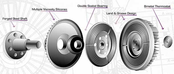
This increases the viscosity between the plates so that it engages the front half of the clutch (Multiple Viscosity Silicone housing). The Severe Duty clutch turns at 80-90% of the water-pump shaft speed, and should be used with deeper pitched fan blades such as 2 1/2-inch or 2 3/4-inch. Standard duty fan clutches turn at 50-60% of water-pump shaft rotation. A 20-inch 7-blade design with a 2-inch pitch is a decent match, for the heavy duty fan clutches such as the Hayden 2747.
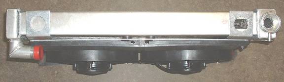
For those of you who wish to replace your current radiator as well, you need at least 1 square inch of radiator surface area per cubic inch of motor, I have an AMC-360 probably bored at .030 over, and my custom 5-core radiator has 410 square inches of surface area. The custom unit is a 5-row, R-Series, punched louvered 13-Fins per inch with a core that is 16-inches high, 25 5/8-inches wide and 2 7/8-inches deep. I chose to use a copper radiator for several reasons, which closely match my driving requirements, yours may differ. The design of my custom radiator is similar to heavy-duty trucks and diesels over the road vehicles, where the core has stamped louvered cooling fins, and the core is fully enclosed by the upper and lower tanks, in a very similar manner as depicted.

I had Dnt Radiators (512) 467-0063 at 705 W. Saint Johns Ave in Austin, TX, custom design a radiator based on the Modine 581 core and it arrived very similar to the core depicted above. This is a very strong design and repairs, should damage occur, should be widely available from Canada to Mexico. I instructed them to make a custom top tank from a copper tube cut in half lengthwise to which they brazed the upper radiator hose fitting and the radiator fill cap to match my old radiator. Finally they brazed the copper tube to the top (left side of picture above) of the industrial radiator core.
Rusty Dodd at Texas Industrial Radiators offers complete Radiator and Fuel Tank service. They are a family owned business, with the grandson taking over the reigns for the family. Rusty and I spent some time discussing the ins-and-outs of radiator design and he states that he can get you a Full Size Jeep radiator (P/N 43-6005) for $194 dollars.
I believe that this is a 4-row hi-density fin unit that will drop right into our Jeeps. Rusty also indicated that he could build a more serious radiator, as the one I have, with a little more investment. You can reach Rusty at (210) 666-5500 @ 5314 IH 10 East San Antonio, Texas 78219. These are good folks and they run a clean family business, with the whole family helping out to run the office. Give them some business, Rusty will work with you to design whatever radiator design and performance levels you specify.
The upper tank of any radiator receives the hottest coolant and here is where steam will be trapped if overheating occurs. My cooling fins completely surround, and are in contact with, the 5-row core of staggered oblong tubes. Each fin adheres to the entire surface area of the tubes, and there are louvers stamped into each fin. There are about 13 cooling fins per vertical inch, which gives plenty of through flow. I have observed that my radiator can cool as much as 40°F from the intake to the outlet, depending on outside ambient air temperatures. I wanted industrial strength and I got it. They used the existing bottom tank from the radiator that they pulled out of the vehicle, as there is little chance of steam forming at this lower location of the cooling system and lower pressure side of the system.
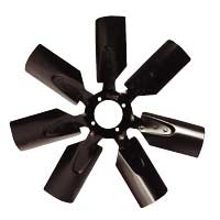
The issue now becomes how to get enough air past that thick radiator that is holding so much heat. A 20-inch 7-blade, 2 3/4 inch pitch fan from a 70-series Dodge 400/440 Motorhome, with a Heavy Duty Fan Clutch is indeed helpful, but this particular fan seems to be fabricated out of a material we all know as unobtainium.
I pulled a 20-inch diameter fan, with 7-blades and with a 2-inch pitch from a GMC truck in a junkyard for cooling. Shown below is a depiction of what you are looking for, 20-inches in diameter and as much pitch as you can find. It will fit an OEM fan shroud, or at least it does on my 1983 Cherokee Laredo, since the OEM fans were 7-blade and 19.5-inches.
A custom fan shroud may just be the ticket here, with a gasket to seal that shroud to the back of the radiator surface. Any self respecting sheet metal shop can fabricate a fan shroud out of stainless steel. The radiator should drop the temperature of the coolant by about 20°- 25° F when the coolant flows through the radiator, at a minimum. This is the difference between the inlet temperature and the outlet temperature of the radiator.
The radiator uses a mechanical rigid blade fan with a fan clutch to keep operating temperatures within operational specifications. The Cherokees, Wagoneers and J-trucks with air conditioning were generally equipped with a Tempatrol fan (7-blades) with fan clutches for both noise control and fan speed control. The fan clutch utilizes a silicon fluid of specific density (depending upon its designation as regular duty, heavy duty or severe duty). Most other engines without air conditioning came with a 4-blade fan.
A fan shroud should be incorporated in order to insure that all of the air being drawn by the fan is pulled through the radiator and not from underneath the vehicle. There are OEM versions available and some of the aftermarket guys on the message boards have been posting pictures of some fabricated sheet metal versions with electric fans.
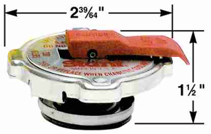
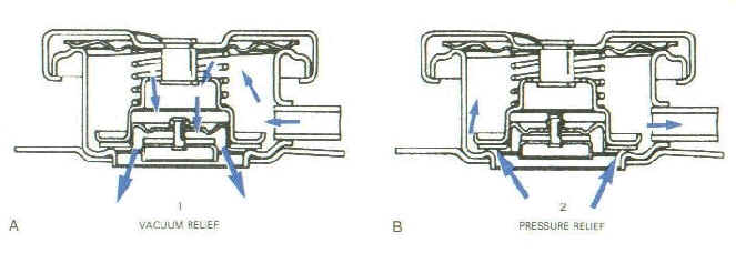
Stant P/N 10330 16-lb Lev-R-Vent Radiator Cap
As you can see from the above and below diagrams, the radiator cap is a pressure relief valve used to relieve pressure and release excessive coolant overflows into a reservoir tank, and also to return the lost fluid from that reservoir tank back into the closed loop system, when the coolant and temps lower and the pressure drops inside of the radiator.
I use a Stant P/N 10330 16-lb Lev-R-Vent Radiator Cap as shown above to further pressurize the coolant to raise the boiling temperature. It also helps provide backpressure on the impeller blades, thus helping to prevent cavitations, a very nasty occurrence.
For every lb of pressure that you impose on the radiator tank, the temperature that the coolant will reach before boiling will be raised by 3° F. So a 16 lb radiator pressure cap will raise the boiling temperature of the water by 48°F from 212° F, which is the normal sea level boiling point of water, to 260° F. This becomes significant due to the fact that if a vehicle looses any coolant, due to boil over and overflow, the system cannot cool down until that coolant, or additional coolant, is replaced back into the system, or until the vehicle is shut down and allowed to cool.
I have a Flowkooler P/N 1781 aluminum high velocity mechanical water pump mated to a modified thermostat, rated at 180° F. Opening the radiator cap, and starting the engine and running her until the thermostat opens up reveals that there is quite a lot of water being moved by the impeller blades of this pump.
Flowkooler P/N 1781
The unit is 4 13/16-inch in depth, with a 5/8-inch shaft protruding out of front to center the pulley and the fan. There are (4) 5/16-inch diameters threaded (18 threads per inch) mounting holes as depicted in the 5A illustration above, the fan bolt mounting holes are on a 3.25-inch center-to-center pattern. The pilot diameter (2 above) is 0.63-inch to center the double pulley and the fan clutch.
It will require the use of BOTH gaskets that ship with the water pump…don't ask me how or why I am positive about this….trust me.
These Flowkooler aluminum water pumps are shipping with an impressive impeller blade, made of brass, that Flowkooler calls their MiraKool M-16. This 16-blade impeller more than doubles the flow rate at idle but drops the flow rate back to the idle when the engine hits 3,500 RPM's, so that cavitations do not occur in the coolant.
Flowkooler 1781 Impeller 16-Blade disk
On my FSJ, I have settled on a Stewart modified Robertshaw thermostat, with a set point of 180° F. My inlet water temperature to the radiator when at 90° F ambient temperature is normally about 195° F, and at the outlet of the radiator, it is about 165°-175° F, during normal engine operations. The below picture depicts a typical Stewart modified Robertshaw thermostat. Make sure you install it with the cone upwards, facing the sky!
One of the more interesting things about fluid dynamics is that if you double the cubic restriction areas that the coolant is allowed to flow thru, and maintain the pressure, you will achieve double the amount of coolant flow. However, if you maintain the restriction to coolant flow and double the pressure, you will raise the amount of coolant flow only by the square root of 1.414. So, a higher flowing water pump in addition to a higher flowing thermostat, in addition to added rows on a radiator makes a lot of sense, eh?
The Stewart/Robertshaw thermostat has three 3/16-inch holes in the cone area of the thermostat, which allows some water to circulate before the thermostat opens. This is great because it allows any trapped air to be transported to the upper radiator tank, rather than being trapped inside the engine passageways where it may form steam pockets.
Stewart modified Robertshaw Thermostat 180° F P/N 301 (195° F P/N 302)
A lot has been said of thermostats in posts, it is interesting to note that some believe that a thermostat with a lower set point temperature, will somehow keep the vehicle cooler.
The OEM specifications call for a 195° F thermostat. I prefer a 180° F in the hot Texas sun. Those of you in the colder climates, especially where it freezes, will want to use the 195° F thermostat, so that the heater will become available faster.
All a thermostat can do is to start opening when their set point has been reached, and begin to close when that temperature set point is higher than the coolant. In the hot Texas and Arizona summers, you want the coolant to begin circulation sooner rather than later.
So a lower 180° F makes some sense. In the freezing northern latitudes, a 195° F thermostat set point makes more sense in the winter months, due to the fact that the block and coolant in the block will reach a higher temperature before the thermostat opens, and therefore the engine will warm up faster and there will be more available heat from the heater core for the occupants. Once the thermostat opens, only its restriction to coolant flow will have any affect on cooling.

Once the thermostat opens, the water flows into the radiator through the cooling fin tubes. Keep in mind that even the highest flowing water pump and associated high flow thermostat can only move as much coolant thru the closed loop systems as the closed loop systems restrictions allow (clogged radiator cooling tubes).
Finally, since pure water is superior to any antifreeze on the market, I tend to use it to more efficiently transfer the heat from the engine to the radiator. Since pure distilled water will soon rust in the system, anti-corrosion additives are needed, and since the water pump likes some lubrication, I use Red Lines WaterWetter® and filtered drinking water for my system, during the Summer months.
Red Line WaterWetter®
The following chart is a depiction of the various materials used in both radiators and coolants; one should pay close attention to the Thermal Conductivity of both Water (0.60) and a 50/50 Anti-freeze/water solution. This clearly shows that water is a superior conductor of heat, and therefore looking at the data one can see how water is a better thermal conductor of heat, it can dissipate a greater amount of heat, and can carry a higher heat load than any other coolant. Therefore it is THE BEST medium to use as a coolant.
Thermal Properties of Cooling System Materials
| Material | Density | Thermal Conductivity | Thermal Convection | Heat Capacity | Heat of Vaporization |
| g/cm3 | Watt/m•°C | Watt/m2•°C | cal/g•°C | cal/g | |
| Water | 1.000 | 0.60 | 1829 | 1.000 | 539 |
| Glycol | 1.114 | 0.25 | ----- | 0.573 | 226 |
| 50/50 | 1.059 | 0.41 | 897 | 0.836 | 374 |
| Aluminum | 2.70 | 155 | 0.225 | ||
| Cast Iron | 7.25 | 58 | 0.119 | ||
| Copper | 8.93 | 84 | 0.093 | ||
| Brass | 8.40 | 113 | 0.091 | ||
| Ceramics | 1-10 | ||||
| Air | .0013 | .026 | 0.240 |
Additionally, the Red Line website (http://www.redlineoil.com/whitePaper/9.pdf) also states "...Under moderate load conditions, each percent glycol raises cylinder head temperatures by 1°F. 50/50% glycol raises head temperatures by 45°F compared to water alone..."
DYNO TEST RESULTS: From the Red Line website...
Dynomometer tests performed by Malcolm Garrett Racing Engines showed significant improvements in coolant temperatures using WaterWetter®. These tests were performed with a Chevrolet 350 V-8 with a cast iron block and aluminum cylinder heads. The thermostat temperature was 160°F. The engine operated at 7200 rpm for three hours and the stabilized cooling system temperature was recorded and tabulated below:
Cooling System Fluid Stabilized Temperature
50% Glycol/ 50% Water 228°F
50/50 with WaterWetter® 220°F
Water 220°F
Water with WaterWetter® 202°F
A strong word of caution here... if your weather conditions include freezing temperatures, then you MUST use some anti-freeze in your system to prevent the coolant from freezing, along with the use of WaterWetter.
From Red Lines website "...Red Line WaterWetter® does not significantly increase the boiling point of water; however, increasing pressure will raise the boiling point. The boiling point of water treated with Red Line using a 15-psi cap is 250° F compared to 265° F at 15 psi for 50% glycol. Increasing the pressure by 50% to 23 psi will increase the boiling point of water to 265° F. Due to the “doubling of the ability” of the coolant to transfer heat, boil over using Red Line treated water is not a problem as long as the engine is circulating coolant through the head and the fan is circulating air. Sudden shutdown after very hard driving may cause boil over..."
Other things to consider are the tendencies of antifreeze additives to decompose, thus adding solvent solids to the coolant mix. Dissolved calcium and lime in tap water are also a bother, as are the mineral contents of tap water in most locations.
Annual or semi-annual changing and flushing out all of these solids on a regular basis eliminates the majority of these problems. The dissolved solids seek the lowest portion of the system that they can locate and reside at, in many cases this leads to build ups being massed just inside the lowest portion of the radiator and available to be sucked in after being jogged loose by traversing rough terrain, thereby being fed directly to the impeller blades of the water pump. Just go out and look at the water jacket of any ole block lying around to see the effects of crud and scale build up, within the water passages.
Use Prestone Super Radiator Cleaner (the one you run for 6-hours) and a back-flush kit added to the Heater Hose inlet hose (from the back of the block) to flush out the cleaner. Then fill with filtered drinking water (4-Gallons in your local grocery store not distilled water), and finally use Red Line WaterWetter instead of anti-freeze in the non-Winter months, and your heating problems will be over. Rust deposits can erode cooling system efficiency by dramatically restricting coolant flow and reducing heat transfer.
These are closed loop cooling systems, and ALL components should be addressed, along with some understanding of the systems operation before going out and throwing parts at the problem.
With the above recommendations, the coolant flows through the radiator faster so it has less time to shed it's heat, BUT it also flows through the block faster, and therefore does not absorb AS MUCH heat...bottom line is that the engine runs cooler.
The WaterWetter prevents the filtered drinking water from forming large bubbles; it increases the tension that the water clings to the internal water passages of the block, thus aiding in heat transfer. Since water has twice the heat transfer capabilities of a 50/50% solution of any kind of anti-freeze and water, you have substantially increased the efficiency of your systems ability to transfer the heat of the engine to the water passing thru it.
Added turbulence from the high flow water pump and higher flowing thermostat scrubs off vaporization areas around exhaust ports and the WaterWetter prevents steam bubbles from forming.
An overall system design approach.
Part Three: Aluminum radiator with Electric Fan\
zack@zmjeeps.com
One of the great things about these Full Size Jeeps is that we have some folks with some expertise available to fall back on. One such individual is our own Zack Heisey (Z&M Jeeps – http://www.zmjeeps.com) who has partnered with Be Cool Aluminum Radiators.
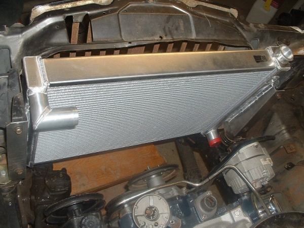
Together they have come up with an ideal turnkey solution in Aluminum radiators for your Jeep. These 100% all aluminum Be Cool cross flow radiators utilize 2-rows with 14 fins per inch. They have two basic models to choose from, a Heavy Duty and a Super Heavy Duty model for both manual and automatic AMC mills. Both models reflect the features mentioned above.
The Heavy Duty models feature a core that is 22-inches Wide by 18.5-inches High and 2.25-inches deep, which gives it a square inch surface area of 407-inches. A 3-inch tank is used. For those of you who wish to convert to an electric fan, there is available a 16-inch shrouded single electric fan that pulls 2360 cfm and draws 20 amps steady state. This will easily cool a 350 HP AMC-360.
The Super Heavy Duty models feature a core that is 24-inches Wide by 18.5-inches High and 2.25-inches deep, which gives it a square inch surface area of 444-inches. The same 3-inch tank is used. This larger cored aluminum radiator is also available with dual electrical 11-inch shrouded fans capable of pulling 2780 cfm at 25 amps steady state.
Another “cool” feature of the Be Cool radiators is that the Radiator Cap is positioned at the “Low Pressure Side” on the cross flow design. The hottest portion of any radiator is the area where the intake or inflow hose from the thermostat is, on the OEM designs; you may have noticed that the radiator caps were pretty much at the hottest possible location.
Some of the readers will recognize that the above Super Heavy Duty model is for a General Motors application. Not to worry, your AMC version will have the correct inlets and outlets so all OEM radiator hoses will work.
You will note that the cross flow design of these radiators feature a high pressure holding tank, and a low pressure holding tank that are both positioned vertically at the ends of the radiator, instead of the top and bottom designed tanks of our OEM designs. Those OEM tanks will get very hot, trapping any steam that might be trapped at the highest point, thus requiring that the radiator caps be replaced more often.
Fluted oval tubes in these cross flow design help stimulate air turbulence to aid in cooling, along with no epoxies, lead or solder, thank you! These radiators can even be fitted with temperature transducer bungs welded into the inflow and outflow tanks per your specifications, just contact Zack @ ZMJeeps to work out the details.

Be Cool suggested using distilled water in their aluminum radiators, and as expected, the Be Cool folks use only the finest manufacturers for their electric fan offerings, in this case, the excellent SPAL Electrical fan offerings.
Zack has engineered a set of radiators to fit AMC, Ford, GM and they all have bungs welded into them for temperature sensors (which are included) when ordered with wiring kits for a total system solution. They have the correct radiator design for either standard or automatic transmissions. Additionally, the GM units are available with a bung on the coolant return line (heater) as well. Take a close look; these units are works of art!
Check out Zack's offerings at his website: http://www.zmjeeps.com.
Zack and Be Cool have partnered together to bring our old Full Size Jeeps cooling designs into the 21st Century, to get started on your specific custom designed aluminum radiator with your specified options, contact Zack directly at .
There it is in a nutshell, see if the approaches outlined in this article do not solve your cooling requirement. Copper for superior strength and aluminum for additional weight savings and tricked out looks, you can have it your way!